Gray Ghost fans, I have very bad news.... The greedy people at photobucket have eliminated viewing of all free account photos that are linked in 3rd party sites. Like this one. Recently, I had been hosting new Gray Ghost photos on Google photos, but I have over 600 photos on photobucket with most used in earlier posts. All of the videos in the sidebar are on photobucket. So, if you try to view an old post and get the error image about me updating my account to a pay account, I apologize. I will eventually migrate all of the photos to Google and reestablish the links, but that will be a big undertaking and will take months.
To say that I am upset by this is an understatement, but just like any other setback when working on the Gray Ghost, I'll persevere. It'll just take a while.
1953 chevy truck ad

Friday, July 14, 2017

Monday, July 3, 2017
HOT : Wiring Progress Update
It's July 3rd, which means its hot and humid out there today. I spent the morning out in the garage working as best as I could. Currently, it is 92 degrees with a feels like temp of 100. The sun was shining into the garage this morning, so there wasn't any break from the heat. I managed about 3 hours out there before I just had to take a brake. In that time, I did make some progress. For example, I permanently mounted the fuse block onto the interior of the firewall. The before and after looks like this:

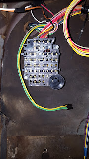
It's a bit of apples to oranges comparison with the wide shot vs close up shot, but you can tell that the clutter from the first shot is gone. So what happened? First off, as I mentioned in my last post, I rotated the fuse block 180 degrees. This put the wires exiting the block toward the openings in the firewall and up under the dash, so that the remaining interior wires could be directly routed towards the gauges, ignition switch and heater. That, all by itself, cleaned things up. Getting the additional wire for the bundles that go through the firewall actually through it also helped clean things up. To actually mount the fuse block to the firewall, it was recommended to me that I build standoffs to elevate the fuse block off of the old firewall padding. I did this by buying a 4 1/2" x 1/4" hex head bolt, some fender washers, nuts and lock nuts. What I did was insert the hex head bolt through the firewall from the engine compartment into the cab and attached 7 nuts to the bolt. This gave the fuse block just over an inch in clearance between the back of the block and the firewall padding. It was capped off with a lock nut so it won't vibrate loose. The above pic is a nice shot of the fuse block without any fuses installed yet. The yellow and green wires hanging down are for the dimmer switch. It will be mounted over the hole that is visible in the bottom of the above pic. The old dimmer switch mounted through the firewall, but the new one sits on top of it. So, I'll have to cover that hole up somehow.
Inside the engine compartment, I separated the wire bundle into groups. One group goes across the compartment to the passenger side, while another group stays on the driver side and a third group goes directly to the engine. The third group is made up of engine sensor connections like water temp, oil pressure and tach. They'll be tucked out of the way until after the engine swap is completed. The wires that were routed to the passenger side include the headlight wires (both high and low beam), right turn signal, ignition switch to starter and wipers. They were all encased in the split wire loom and routed across the firewall using factory clips. At this point, I've run out of the split wire loom and will have to buy some more. This time,though, I'll get 1 size smaller as I have fewer wires to encase on the driver's side. All in all it's starting to get organized and looks like this:


Before

After

It's a bit of apples to oranges comparison with the wide shot vs close up shot, but you can tell that the clutter from the first shot is gone. So what happened? First off, as I mentioned in my last post, I rotated the fuse block 180 degrees. This put the wires exiting the block toward the openings in the firewall and up under the dash, so that the remaining interior wires could be directly routed towards the gauges, ignition switch and heater. That, all by itself, cleaned things up. Getting the additional wire for the bundles that go through the firewall actually through it also helped clean things up. To actually mount the fuse block to the firewall, it was recommended to me that I build standoffs to elevate the fuse block off of the old firewall padding. I did this by buying a 4 1/2" x 1/4" hex head bolt, some fender washers, nuts and lock nuts. What I did was insert the hex head bolt through the firewall from the engine compartment into the cab and attached 7 nuts to the bolt. This gave the fuse block just over an inch in clearance between the back of the block and the firewall padding. It was capped off with a lock nut so it won't vibrate loose. The above pic is a nice shot of the fuse block without any fuses installed yet. The yellow and green wires hanging down are for the dimmer switch. It will be mounted over the hole that is visible in the bottom of the above pic. The old dimmer switch mounted through the firewall, but the new one sits on top of it. So, I'll have to cover that hole up somehow.
Inside the engine compartment, I separated the wire bundle into groups. One group goes across the compartment to the passenger side, while another group stays on the driver side and a third group goes directly to the engine. The third group is made up of engine sensor connections like water temp, oil pressure and tach. They'll be tucked out of the way until after the engine swap is completed. The wires that were routed to the passenger side include the headlight wires (both high and low beam), right turn signal, ignition switch to starter and wipers. They were all encased in the split wire loom and routed across the firewall using factory clips. At this point, I've run out of the split wire loom and will have to buy some more. This time,though, I'll get 1 size smaller as I have fewer wires to encase on the driver's side. All in all it's starting to get organized and looks like this:
Before

After

The wires splitting off of the center bundle are brake light wires and go to the brake light switch which is mounted to the engine side of the firewall. These include the third brake light, which I'm going to use. I have a special plan for the third brake light assembly, but that is a surprise for a later post! The rest of that bundle includes all of the "rear of the truck" wires. The blue and brown wires splitting off from the rightmost bundle include the left turn signal and park light. All of the other wires on the right are for the engine sensors and tach. I will likely route those under the other wires that cross over the firewall in a separate loom and take them straight to the engine. Another thing that is visible here are the hex bolts and fender washers. I was able to reuse one of the existing holes in the firewall to mount the fuse block. However, I did have to drill a second one to match the mounting hole pattern.
It's a truism that nothing just bolts right up, even if its supposed to! The most recent case in point is the headlight switch. The new switch is designed to work exactly and even had the anti-rotation tab in the right spot. Held up to the inside of the dash it looked like this:

You can notice the square tab to the side of the hole. The switch has a tab that fits in that square part and keeps the whole thing from rotating when you turn the knob to activate the dome light. The problem was that the decorative nut that goes through the hole and screws onto the switch had a gap when fully seated. This meant that the switch flopped around in the opening. The gap looked like this:

To solve the problem, I got a large washer to fill the space. But since it would be on the outside of the dash, it would be visible. That would look kinda tacky having a nice painted dash and a grade 8 washer for all to see. The solution was to paint the washer. You know I love my pics so here goes:

Nice transformation from the normal look of a grade 8 item to a nice Gray Ghost painted dark bronze! I'm still waiting for the paint to fully cure and harden. It's so hot out there in the garage that I'll probably be able to put it on tomorrow without scratching any of it.
Also today, the mailman brought a couple of special deliveries! I had ruined the original cylinder lock trying to get it out of the original ignition switch. So a new one was in order. It came today and with a little figuring, I was able to get it into the new ignition switch. So that part is now ready to be connected to the new wire harness and installed into the dash. Those wires already have been terminated and have the female end for spade connectors which fit onto the new switch.
Another item that came in that package were the Chevrolet letter decals for the dash trim. I figured that since I was already placing an order, why not get them. I've been wanting to finish off that piece of the trim for months, but had no reason to place an order. So I just waited. Once they got here, it was short work to get them on. Before and after looked like this:
Before

After

Other than the flash washing out the center, they aren't too shabby. Although, to be honest, they are 10 foot decals, not 10x magnification decals as they don't exactly fit into the stock spaces. But for my purposes I was pretty happy. Now back down to the basement for that piece until I'm finally ready for it!
That's all for now. Happy 4th of July, Everyone! Happy Birthday, America!
Saturday, July 1, 2017
Old Grommets and New Wires
Yesterday was a big day in the garage, Gray Ghost fans! It marked the beginning of the new wire harness installation. In preparing for the installation, I read and reread the installation instructions and tried to match up as much of the wiring and associated hardware as possible. Here is the stuff before I spread it out as I prepped:

What I have is a Speedway Motors universal wire harness, Rebel Wiring headlight relay and a period correct turn signal switch. Also visible are the wire harnesses and sensor connectors for my New Vintage gauges! A sharp eye will also catch the LED flashers in the box. I have to switch to those because I'm using LED bulbs in the turn signals and tail lights.
I had already decided that I would route all of the wires using the factory locations. That helped me locate where I had to place the new fuse holder. I ended up using one of the old fuse holder holes and drilling out the second hole for the other attaching bolt. However, prior to attaching the fuse holder, I had a lot of wires to pull through those grommets. Inside the engine compartment, it looked like this:

On the right, you can see most of the engine compartment wires. There are still a couple of engine related wires to install, but they will likely wait until after the engine swap is done. The engine compartment wires include headlight wires, ignition wires and brake light wires. The wires on the left are rear of the truck wires and include tail light wires and third brake light wires. I ran them in some split wire loom, to protect them, through the factory locations.
Inside the cab, the wires are just kinda roughed in at the moment. It currently looks like this:

Since this photo was taken, I've decided to rotate the fuse block. It made more sense to put it that way, since it put the wires exiting the fuse block pointing towards the firewall holes. It also gave me some more slack on the dome light wires. Yesterday, when I ran those wires, they came up a bit short of the required location. It looked like this:

In this pic you can see that I used the old wire as fish tape and was able to pull the new wires up from the under dash area, through the A pillar and to the channel above the door and to the rear of the truck. That is the factory routing. Even with the extra slack, I think I'll be a bit short and will have to extend them. So far, that is the only issue that I've encountered with the Speedway harness. Overall, I've been very impressed with the harness. The wire colors follow the GM convention and are labeled every foot or so. The instruction sheets are pretty thorough and easy to follow. Now, the aftermarket turn signal switch was another story.... Those instructions left a little to be desired. I think I've got it figured out, but I won't know for sure until I put power to the new system. That is some time away.
Next on the agenda is to get the wires into their final, factory locations and to make each of the wire connections. That will probably take some time as I want to take my time and do it right.

What I have is a Speedway Motors universal wire harness, Rebel Wiring headlight relay and a period correct turn signal switch. Also visible are the wire harnesses and sensor connectors for my New Vintage gauges! A sharp eye will also catch the LED flashers in the box. I have to switch to those because I'm using LED bulbs in the turn signals and tail lights.
I had already decided that I would route all of the wires using the factory locations. That helped me locate where I had to place the new fuse holder. I ended up using one of the old fuse holder holes and drilling out the second hole for the other attaching bolt. However, prior to attaching the fuse holder, I had a lot of wires to pull through those grommets. Inside the engine compartment, it looked like this:

Inside the cab, the wires are just kinda roughed in at the moment. It currently looks like this:

Since this photo was taken, I've decided to rotate the fuse block. It made more sense to put it that way, since it put the wires exiting the fuse block pointing towards the firewall holes. It also gave me some more slack on the dome light wires. Yesterday, when I ran those wires, they came up a bit short of the required location. It looked like this:

In this pic you can see that I used the old wire as fish tape and was able to pull the new wires up from the under dash area, through the A pillar and to the channel above the door and to the rear of the truck. That is the factory routing. Even with the extra slack, I think I'll be a bit short and will have to extend them. So far, that is the only issue that I've encountered with the Speedway harness. Overall, I've been very impressed with the harness. The wire colors follow the GM convention and are labeled every foot or so. The instruction sheets are pretty thorough and easy to follow. Now, the aftermarket turn signal switch was another story.... Those instructions left a little to be desired. I think I've got it figured out, but I won't know for sure until I put power to the new system. That is some time away.
Next on the agenda is to get the wires into their final, factory locations and to make each of the wire connections. That will probably take some time as I want to take my time and do it right.
Friday, June 9, 2017
Electrical Demolition in the Gray Ghost is Complete!
Well, that was easy! Really! The old electrical wiring is now gone. The only difficulty was a couple of stubborn clutch head screws in the engine compartment that were holding the fuse holders to the firewall. It was likely that they had never been touched after production in 1953. Anyway, it is all out now and in the recycle bin. The only exceptions were non-wire components. They were saved for the future, if a future owner wanted original components. These included the external voltage regulator, fuse holders, dimmer switch, turn signal switch and the gauge light bulb holders. Everything else is gone. Here it is, laying on the garage floor:

The circular bundle are the tail light wires. The tan wires to the left of that are headlight wires. The engine compartment wires/cab interior wires are at the top of the photo. The wire harness at the bottom is from the starter to the firewall. I had to cut the bundle to get them through the firewall.
Next steps:
I have to buy the split wire loom to protect the new wires and the loom holders that attach it to the frame of the truck. I also need some wire solder and flux. I have figured out where on the firewall to locate the new fuse panel. Actually, it has to be on the inside of the cab, not in the engine compartment. Also, I need to arrange the new wire bundle so that the wires go out of the correct holes in the firewall. What I mean by that is that wires that go to the starter go through one hole and wires that go to the headlights or to the rear of the truck go through a different hole. Cab interior wires don't go through the firewall, they get routed to their respective locations (ie, headlight switch, dome light, instrument gauges, heater, etc).
Once I get started on that, I'll make another post.

The circular bundle are the tail light wires. The tan wires to the left of that are headlight wires. The engine compartment wires/cab interior wires are at the top of the photo. The wire harness at the bottom is from the starter to the firewall. I had to cut the bundle to get them through the firewall.
Next steps:
I have to buy the split wire loom to protect the new wires and the loom holders that attach it to the frame of the truck. I also need some wire solder and flux. I have figured out where on the firewall to locate the new fuse panel. Actually, it has to be on the inside of the cab, not in the engine compartment. Also, I need to arrange the new wire bundle so that the wires go out of the correct holes in the firewall. What I mean by that is that wires that go to the starter go through one hole and wires that go to the headlights or to the rear of the truck go through a different hole. Cab interior wires don't go through the firewall, they get routed to their respective locations (ie, headlight switch, dome light, instrument gauges, heater, etc).
Once I get started on that, I'll make another post.
Sunday, June 4, 2017
The Gray Ghost Can Park or Not!
Well, Gray Ghost fans, I have good news! No pictures today, but definitely good news. After reading the shop manual many, many times and thinking it through many, many times, I finally think I've figured out what the GM engineers wanted me to know. The end result is that it appears that I have successfully installed the park brake cables on both back brakes drums and properly adjusted the normal brakes and the park brakes! What a relief! As I mentioned in my last post, this project was started last January. It seemed like it would be such a simple job. Not so much. The whole thing fought me at every turn. To be honest, some of my time in between January and June was spent sandblasting parts from the pile. Plus a little clean up in the cab. But now, it is done. When the park brake pedal is fully depressed, the back wheels do not turn. When it is released, the turn freely. When the normal brake pedal is depressed, the wheels stop turning. Who could ask for more?!?
What's up next on the Gray Ghost agenda? Wiring! I have a brand new wire harness to install. If you were alert, you would have noticed stray wires hanging down in one of the interior pics from an earlier post. If you were really alert, you would have noticed that one of those wires is actually an indoor extension cord wire! Yes, a previous owner used an old extension cord to wire in something.... No matter, it's all going. After the wiring...wait for it...time to swap engines! Being realistic, or at least trying to be realistic, if I can get the engine swapped out before the cold weather I will have really done something. Yes, it is only the first week of June. But my time is limited and I still need to buy some supplies for the electrical work. Then I need to do the work. Once that is done, I can turn my attention to removing the transmission. Once that is out, I can work on getting the flywheel surfaced and ready for the replacement engine. Then I'll need to buy a new clutch assembly. So I've got a little saving to do and a little work. Something to keep me going through the summer.
That's all for now. Back when I have some news.

What's up next on the Gray Ghost agenda? Wiring! I have a brand new wire harness to install. If you were alert, you would have noticed stray wires hanging down in one of the interior pics from an earlier post. If you were really alert, you would have noticed that one of those wires is actually an indoor extension cord wire! Yes, a previous owner used an old extension cord to wire in something.... No matter, it's all going. After the wiring...wait for it...time to swap engines! Being realistic, or at least trying to be realistic, if I can get the engine swapped out before the cold weather I will have really done something. Yes, it is only the first week of June. But my time is limited and I still need to buy some supplies for the electrical work. Then I need to do the work. Once that is done, I can turn my attention to removing the transmission. Once that is out, I can work on getting the flywheel surfaced and ready for the replacement engine. Then I'll need to buy a new clutch assembly. So I've got a little saving to do and a little work. Something to keep me going through the summer.
That's all for now. Back when I have some news.
Happy summer!

Friday, May 26, 2017
Parking Brake Woes Park the Gray Ghost
Welcome back Gray Ghost fans! It's been a couple of months since my last update and I've made some progress. Although not as much progress as I would have liked. The project that has had me tied up for so many months is installation of the park brake cables. In retrospect, it probably would have been easier to do both the park brake cables and the brake shoe replacement all at the same time. I didn't have the cables back then and I just went for it on the brake shoes. I always knew I'd have to take things apart once I got the cables. I got the cables last Christmas, so back in January I got started. Yes, you read that right. January! It is now Memorial Day weekend and I'm sad to report that I'm still not done! I did make significant progress today, so I figured I'd give a status report. It's sort of a tragic comedy.
Act 1
Getting things back apart in the drum was easy. Disconnecting the park brake lever from the brake shoes was nothing more than removing a bolt. Disconnecting the cable from the lever was relatively easy, too. It was under spring tension, so a little persuasion was necessary. Next came removing the cable backing plate from the brake housing backing plate. Two screws to remove and off it came. So far, so good! Then came removing the cable from the cast iron bracket that is riveted to the frame. (Cue the dire sounding music now....) This was not going to be easy. The cable and bracket looked like this:

The silver lining in this cloud is that after soaking in Kroil for a very long time, the nut and bolt came apart! That, is the only silver around here. As you can see, the cable is rusted in place. Looking at the cable, the front of the truck is to the right. The front part of the cable is where the clevis connects to the cable and then to the crossmember that activates the park brake when the pedal is depressed.
Long story short, I used wire cutters and cut the front part of the cable off and soaked the bracket cable in more Kroil and left for the week. When I came back, I was able to use the ball pein hammer and a punch to get the rusted part of the cable out of the bracket. Smooth sailing surely must be ahead now.
Well, not so much. The first part of the installation was pretty straight forward. Insert the brake drum end of the cable through the backer plate, add the felt washer and screw it in place. Then attach the cable to the park brake lever. The new cable and washer looked like this:

When I went to slide the new cable into the bracket I found that the ferrule on the new cable was just, ever so slightly, too big to fit into the bracket. Go figure. I tried using a pry bar to open up the bracket, for which I was soundly chastised by my truck forum friends. They reminded me that it is cast iron and doesn't take kindly to being pried. I tried gently grinding some of the ferrule. That didn't work either. I tried getting my Dremel with a chainsaw sharpening grinder attached, but there wasn't enough room to fit the Dremel in place. The cable bracket needed to be adjusted, there was no doubt about that. Here's what the cable/bracket looked like at this point:

Clearly it didn't fit. But of an even greater problem is that without moving to the end of the bracket, the cable wasn't long enough to connect to the clevis and crossmember! Here's how far apart they were:

So, I was left with a small rat tail file. Laying on the creeper for over 2 hours and filing a little, then testing the fit and then repeating, I finally got the ferrule to fit into the bracket. Even then, I had to lubricate the ferrule and bracket for it to go in. Now, Gray Ghost fans, don't be fooled into thinking that this was a quick process. Far from it. The next pic shows the cable finally connected to the clevis and the crossmember. This pic was taken in...April. Anyway, here it is:

Here you can see the whole arrangement. The bracket with the cable fully seated, the new grade 8 hardware cinching it down, the threaded rod end of the cable, 2 jam nuts, the clevis, clevis pin and cotter key. The cotter key is just set in place, as I have to remove the clevis from the crossmember to adjust the brake shoes, but that is in the future, as I'm not ready yet. I've still got the driver's side to do! OMG!
Yeah, it is kind of a groundhog day type of thing. I got into the driver's side brake drum, got it all apart, got the new cable installed and then the wheels came off the wagon. Bigtime or Bigly if you like that. The issue has to do with the "spreader bar" and the orientation of the spring that goes around it. It looks like this:

OBTW, it is installed WRONG! It took me days to figure out about how it had to be positioned. Couple that with a busy schedule and it took me another 2 weeks to get around to actually fixing it.
Intermission
Here's a fun shot of the 2 old clevis connectors and cables:

Act 2
Installation of the cable in the driver's side bracket...yes it takes the same trajectory as the passenger side. Four hours later, it is in place. Now,and only now, am I able to go back and adjust the brake shoes in each drum. After that is done, there is an adjustment to the park brakes that I'll need to do. However, before I can do that, I need to figure out what the shop manual is trying to tell me about the process. At the time of this writing, I have no clue. Even though I've read it several times.
So here we are, 5 months into this process and I'd call it about 50% done. Maybe less if I messed up the fluid pressure in the brake lines and they have to be bled again. Grand total of labor hours to get to the 50% point is pushing 40 hours. Brothers and Sisters, let us pray!
Act 1
Getting things back apart in the drum was easy. Disconnecting the park brake lever from the brake shoes was nothing more than removing a bolt. Disconnecting the cable from the lever was relatively easy, too. It was under spring tension, so a little persuasion was necessary. Next came removing the cable backing plate from the brake housing backing plate. Two screws to remove and off it came. So far, so good! Then came removing the cable from the cast iron bracket that is riveted to the frame. (Cue the dire sounding music now....) This was not going to be easy. The cable and bracket looked like this:

The silver lining in this cloud is that after soaking in Kroil for a very long time, the nut and bolt came apart! That, is the only silver around here. As you can see, the cable is rusted in place. Looking at the cable, the front of the truck is to the right. The front part of the cable is where the clevis connects to the cable and then to the crossmember that activates the park brake when the pedal is depressed.
Long story short, I used wire cutters and cut the front part of the cable off and soaked the bracket cable in more Kroil and left for the week. When I came back, I was able to use the ball pein hammer and a punch to get the rusted part of the cable out of the bracket. Smooth sailing surely must be ahead now.
Well, not so much. The first part of the installation was pretty straight forward. Insert the brake drum end of the cable through the backer plate, add the felt washer and screw it in place. Then attach the cable to the park brake lever. The new cable and washer looked like this:

When I went to slide the new cable into the bracket I found that the ferrule on the new cable was just, ever so slightly, too big to fit into the bracket. Go figure. I tried using a pry bar to open up the bracket, for which I was soundly chastised by my truck forum friends. They reminded me that it is cast iron and doesn't take kindly to being pried. I tried gently grinding some of the ferrule. That didn't work either. I tried getting my Dremel with a chainsaw sharpening grinder attached, but there wasn't enough room to fit the Dremel in place. The cable bracket needed to be adjusted, there was no doubt about that. Here's what the cable/bracket looked like at this point:

Clearly it didn't fit. But of an even greater problem is that without moving to the end of the bracket, the cable wasn't long enough to connect to the clevis and crossmember! Here's how far apart they were:

So, I was left with a small rat tail file. Laying on the creeper for over 2 hours and filing a little, then testing the fit and then repeating, I finally got the ferrule to fit into the bracket. Even then, I had to lubricate the ferrule and bracket for it to go in. Now, Gray Ghost fans, don't be fooled into thinking that this was a quick process. Far from it. The next pic shows the cable finally connected to the clevis and the crossmember. This pic was taken in...April. Anyway, here it is:

Here you can see the whole arrangement. The bracket with the cable fully seated, the new grade 8 hardware cinching it down, the threaded rod end of the cable, 2 jam nuts, the clevis, clevis pin and cotter key. The cotter key is just set in place, as I have to remove the clevis from the crossmember to adjust the brake shoes, but that is in the future, as I'm not ready yet. I've still got the driver's side to do! OMG!
Yeah, it is kind of a groundhog day type of thing. I got into the driver's side brake drum, got it all apart, got the new cable installed and then the wheels came off the wagon. Bigtime or Bigly if you like that. The issue has to do with the "spreader bar" and the orientation of the spring that goes around it. It looks like this:

OBTW, it is installed WRONG! It took me days to figure out about how it had to be positioned. Couple that with a busy schedule and it took me another 2 weeks to get around to actually fixing it.
Intermission
Here's a fun shot of the 2 old clevis connectors and cables:

Act 2
Installation of the cable in the driver's side bracket...yes it takes the same trajectory as the passenger side. Four hours later, it is in place. Now,and only now, am I able to go back and adjust the brake shoes in each drum. After that is done, there is an adjustment to the park brakes that I'll need to do. However, before I can do that, I need to figure out what the shop manual is trying to tell me about the process. At the time of this writing, I have no clue. Even though I've read it several times.
So here we are, 5 months into this process and I'd call it about 50% done. Maybe less if I messed up the fluid pressure in the brake lines and they have to be bled again. Grand total of labor hours to get to the 50% point is pushing 40 hours. Brothers and Sisters, let us pray!
Saturday, February 25, 2017
Sandblasting...Good for the Soul And Not Bad For Rust Removal Either
Well Gray Ghost fans, yesterday I got to do what I've been dreaming about doing lo these many years. Sandblast rust from the Gray Ghost! But before I got started blasting, I wanted to do some mods to my Harbor Freight blast cabinet. There are tons of mods that people have done on Youtube, but the one that really got my attention was adding the wheels to the cabinet, so you can roll it around the shop. I did it just like the video and it turned out like this:

How slick is that? The wheels also came from Harbor Freight. I used 5/8" allthread with 8 washers and 8 nuts to hold it all together. To get the height that I needed , I set the 2 legs onto 1-by stock, which raised them up just enough that the wheels can rotate, but not so much that the cabinet is noticeably leaning to 1 side.
The next mod didn't work out quite like I wanted.... That mod was to add dust removal from inside the cabinet to improve visibility while I was blasting. I made an attempt at making my own dust separator using a 5 gallon bucket and a shopvac. The idea is to create a vortex separator in the bucket to trap the debris and dust so that essentially clean air goes to the shopvac and keeps the filter from getting clogged up. My setup looked like this:


The hose connects to the port that is built into the blast cabinet and runs to the 5 gallon bucket. Hmmm, it just occurred to me, while looking at the pics, that I did it exactly backwards!!! Holy crap! The hose from the cabinet is supposed to run to the port on the side of the bucket. The port is supposed to be angled to cause the air to flow around the sides of the bucket which causes the debris to fall out and not get sucked into the shopvac. Well, ain't that a kick in the pants! I'll have to remember to switch that around next time out! Definitely staying true to my goal of the good, bad and ugly. I think we can all agree that was ugly. So, on to the good!
With that beast of a compressor, that blast cabinet really cuts through the crud! As my test subjects, I used the panel covers from both doors. These covers are at the bottom of each door and were really gnarly. Here is the passenger side door panel cover (front and back) before blasting:


Pretty rough shape. Rust, layers of old paint, the ever present primer that the previous owner sprayed on everything.... So how is a blast cabinet going to cut through that? With aluminum oxide grit, that's how! Here are the after blasting shots:


The dark discoloration in the pics is the mineral spirits that hadn't evaporated before I took the pics. After blasting, they got a good wipe down with mineral spirits to remove any dust or grit that might have remained on them. From here, it was straight to primer. It looked like this:

The panel is suspended from a rod between 2 lawn chairs by some old fishing line. Made for perfect paint application, sort of. It was a bit breezy out, so I had to spray in between gusts of wind, but it worked out pretty good. After the primer, it was straight to color. It looked like this:

This is the same dark bronze color that the cab interior and doors were painted. I used new, stainless steel screws to reattach the panel to the door. I had thought about regular screws that were painted, but decided to accentuate the connection with shiny stainless steel screws. No pic of that, yet, as I was short of time then. I'll make sure to get a shot of it when I get the interior finished up. That's a ways off.
What a time saving tool the blast cabinet turned out to be. Yes, I could have used sand paper, a wire brush or a grinder, but this really is the right tool for this job.
Why is sandblasting good for the soul you might ask? Easy. Watching all of the layers of paint and rust just evaporate was like watching all of my cares at work go away with the rust. Instant gratification. A dream that came to fruition, exactly as I had hoped that it would. Promise, that I can finish the restoration work on this truck and that it will be something that I can be proud of. Not bad for 1 little blast cabinet and a beast of a compressor.

How slick is that? The wheels also came from Harbor Freight. I used 5/8" allthread with 8 washers and 8 nuts to hold it all together. To get the height that I needed , I set the 2 legs onto 1-by stock, which raised them up just enough that the wheels can rotate, but not so much that the cabinet is noticeably leaning to 1 side.
The next mod didn't work out quite like I wanted.... That mod was to add dust removal from inside the cabinet to improve visibility while I was blasting. I made an attempt at making my own dust separator using a 5 gallon bucket and a shopvac. The idea is to create a vortex separator in the bucket to trap the debris and dust so that essentially clean air goes to the shopvac and keeps the filter from getting clogged up. My setup looked like this:


The hose connects to the port that is built into the blast cabinet and runs to the 5 gallon bucket. Hmmm, it just occurred to me, while looking at the pics, that I did it exactly backwards!!! Holy crap! The hose from the cabinet is supposed to run to the port on the side of the bucket. The port is supposed to be angled to cause the air to flow around the sides of the bucket which causes the debris to fall out and not get sucked into the shopvac. Well, ain't that a kick in the pants! I'll have to remember to switch that around next time out! Definitely staying true to my goal of the good, bad and ugly. I think we can all agree that was ugly. So, on to the good!
With that beast of a compressor, that blast cabinet really cuts through the crud! As my test subjects, I used the panel covers from both doors. These covers are at the bottom of each door and were really gnarly. Here is the passenger side door panel cover (front and back) before blasting:


Pretty rough shape. Rust, layers of old paint, the ever present primer that the previous owner sprayed on everything.... So how is a blast cabinet going to cut through that? With aluminum oxide grit, that's how! Here are the after blasting shots:


The dark discoloration in the pics is the mineral spirits that hadn't evaporated before I took the pics. After blasting, they got a good wipe down with mineral spirits to remove any dust or grit that might have remained on them. From here, it was straight to primer. It looked like this:

The panel is suspended from a rod between 2 lawn chairs by some old fishing line. Made for perfect paint application, sort of. It was a bit breezy out, so I had to spray in between gusts of wind, but it worked out pretty good. After the primer, it was straight to color. It looked like this:

This is the same dark bronze color that the cab interior and doors were painted. I used new, stainless steel screws to reattach the panel to the door. I had thought about regular screws that were painted, but decided to accentuate the connection with shiny stainless steel screws. No pic of that, yet, as I was short of time then. I'll make sure to get a shot of it when I get the interior finished up. That's a ways off.
What a time saving tool the blast cabinet turned out to be. Yes, I could have used sand paper, a wire brush or a grinder, but this really is the right tool for this job.
Why is sandblasting good for the soul you might ask? Easy. Watching all of the layers of paint and rust just evaporate was like watching all of my cares at work go away with the rust. Instant gratification. A dream that came to fruition, exactly as I had hoped that it would. Promise, that I can finish the restoration work on this truck and that it will be something that I can be proud of. Not bad for 1 little blast cabinet and a beast of a compressor.
Monday, January 30, 2017
Feeling The Pressure of Compressor Installation

I thought I'd start out with a soothing winter scene. This is the view from my front porch this morning. We had a light snowfall overnight that left a very scenic view. Now, on to the news.
Once again, in keeping with the intent of this blog, to report the good, the bad and the ugly in my restoration adventure, this post has it all...!
First the good. My beast of a compressor is now a runner! As proof, I offer the following short video clip:
It's pretty loud in the background of this clip. The audio is so loud, because the installation instructions directed me to run the compressor for 30 minutes with the valves wide open. After the 30 minute break in period, you close the valves and let it build up pressure until the cut off switch turns off the compressor. All in all, it worked perfectly.
Second, the bad: I bought this compressor in December of...wait for it...2011. Yes, it took me 5 years to get around to having an electrician actually hook it up to the breaker panel.
Lastly, the ugly. Why the heck did it take me 5 years to get the bloody thing hoked up?!? Well, like most everything else in life, there is no single answer. Mostly, though, it was just everyday life. As I've mentioned in other posts, I tend to be pretty busy, so I just didn't miss it. Now, I've got a 1953 Chevy pickup truck with the bed full of stuff that needs to be blasted clean so it can be painted and reinstalled on the truck. So it finally became a need.
No matter. It's still mine and now it's hooked up, fully functional and ready for when I've got the time to work on the truck. I have to say, too, it's pretty impressive.
The specs:
5 HP motor
80 gallon tank
15.5 CFM flow at 90 psi
100% duty cycle (since I'm using the synthetic oil)
I'm pretty sure it'll handle whatever I can throw at it at the moment. Maybe down the road, when I tear it apart for the frame off restoration, that sand blasting will test it. But until then, I feel pretty comfortable doing whatever I need that requires compressed air.
Once I start doing some blasting, I'll post some before and after pics.
That's all for now.
Monday, January 16, 2017
Errant Hole No More!
UPDATE:
After conferring with a specialist...actually, a Home Depot associate...I've got a fix installed for my errant hole. Only time will tell if it's a good fix, but it's done. So nothing left but the crying, as they say. The solution was to put another concrete anchor down the errant hole. I used some heavy duty epoxy to fill any gaps between the concrete anchor and the sides of the hole. Hopefully it's enough to keep the the small amount of concrete between the holes from blowing out and making one unsuitable hole. Anyway, here's how it looked with the fix installed:

Here you can see that the anchor was trimmed so that it would be flush with the floor. You can also see the epoxy around the anchor. You can also see that there's still a little concrete powder in the other hole. I did get most of it out, after the picture was taken. It looks like maybe a 1/2" of concrete between the holes, maybe a bit more, but I didn't measure, so I'm not sure. And now, it's too late! After a day of curing, I got my son to help me reposition the compressor over the holes. Then we carefully tipped the compressor to raise one foot at a time, so that we could put the vibration insulator pads under each foot. Once that was done, I made sure that each hole in the concrete was aligned with the hole in the vibration isolation pad (which, by the way, I had to drill my self) and the hole in the compressor foot. It took a bit of fiddling about with the 600 lb (ish) compressor, but eventually all holes lined up and I pounded the concrete anchors into place. Once it was all done it looked like this:

In the background, you can see the blue conduit. Inside the conduit is the electrical wire that will connect the compressor to the breaker panel. So...the next step is to plumb the air outlet to a pressure regulator so that I can use the compressor, finally! Eventually, I'll set up an air system for the garage, but for now, I've got projects that require this air, so a temporary hook up is all I need. That's all for now. Once I get the power hooked up, I'll take a video of the break in. Can't wait!
After conferring with a specialist...actually, a Home Depot associate...I've got a fix installed for my errant hole. Only time will tell if it's a good fix, but it's done. So nothing left but the crying, as they say. The solution was to put another concrete anchor down the errant hole. I used some heavy duty epoxy to fill any gaps between the concrete anchor and the sides of the hole. Hopefully it's enough to keep the the small amount of concrete between the holes from blowing out and making one unsuitable hole. Anyway, here's how it looked with the fix installed:

Here you can see that the anchor was trimmed so that it would be flush with the floor. You can also see the epoxy around the anchor. You can also see that there's still a little concrete powder in the other hole. I did get most of it out, after the picture was taken. It looks like maybe a 1/2" of concrete between the holes, maybe a bit more, but I didn't measure, so I'm not sure. And now, it's too late! After a day of curing, I got my son to help me reposition the compressor over the holes. Then we carefully tipped the compressor to raise one foot at a time, so that we could put the vibration insulator pads under each foot. Once that was done, I made sure that each hole in the concrete was aligned with the hole in the vibration isolation pad (which, by the way, I had to drill my self) and the hole in the compressor foot. It took a bit of fiddling about with the 600 lb (ish) compressor, but eventually all holes lined up and I pounded the concrete anchors into place. Once it was all done it looked like this:

In the background, you can see the blue conduit. Inside the conduit is the electrical wire that will connect the compressor to the breaker panel. So...the next step is to plumb the air outlet to a pressure regulator so that I can use the compressor, finally! Eventually, I'll set up an air system for the garage, but for now, I've got projects that require this air, so a temporary hook up is all I need. That's all for now. Once I get the power hooked up, I'll take a video of the break in. Can't wait!
Saturday, January 14, 2017
An Errant Hole...That Can't Be Good!
Well, to remain true to my original goal of reporting the good, bad and ugly of my restoration adventure, I sadly have some bad news to report. Hopefully, down the road it doesn't turn into ugly news.
Where it all began: I decided that I needed a good compressor. Pretty reasonable, considering the adventure that I was beginning. So, I did my research and decided on an Ingersoll Rand 80 gallon, 5 HP beast. Go big or go home! When I got it, I had to do a bunch of research on how it needed to be installed. Meaning electrical requirements and how to plumb the air for my garage. Then, time passes...money gets spent on other things...and hooking up your compressor gets onto the todo list and seemingly never gets done.
Then, one day, you have an electrical problem with the pump on your septic tank. While the electrician is there, he sees your cool, old truck and the compressor sitting idle in the back of your garage and asks why it isn't hooked up? Slightly embarrassed, you explain. He informs you, that it's only about 30 minutes of labor to do the electrical work, if you run the wire prior to their arrival. That creates the spark to get this installed and functional!
The list:
1. vibration isolation pads
2. concrete anchors
3. 6 gauge wire
4. conduit
5. 220v circuit breaker to match my electrical panel
6. Ingersoll Rand compressor break in kit (synthetic oil and air filters)
Slowly, but surely, I got the items on the list. The wire is run from the breaker panel side of the garage to where the compressor will be bolted to the floor and it is encased in conduit. That meant it was time to bolt the compressor to the floor.
The installation instructions that came with the compressor state that it should be at least 1 foot from all walls. So, I measured out 1 foot from the back wall, measured the top sides of the compressor to make sure that each side was equidistant from the wall and marked where each hole should be. Based on the size of the compressor, I used 5/8" concrete anchors and bought the appropriate masonry drill bit. Combined with my hammer drill, I assumed it wouldn't be too difficult a task. Hole #1 wasn't too difficult and took about 10 minutes from start to finish. Hole #2 started off that way, but ran into a bit of a snag when I hit a stone about an inch into the hole. Even with the hammer action and me leaning onto the drill it took more than 10 minutes to bore through it. Once I did, the rest of the hole was easy sailing. On to hole #3. Following the same procedure that I had used for the first two holes, I started the drilling by not using the hammer function. The top of the concrete does not require the hammer function. I drilled down about a quarter of an inch and then switched on the hammer function. What I did not notice was that when the hammering started, the drill bit skipped out of the hole that I had started and was now in the wrong location! Once I figured it out, it was too late. The situation looked grim. I rotated the compressor back into position and saw what I expected to see. Holes #1 and #2 were in exactly the right spots and #3 was off. With the compressor sitting where it needed to be, I did notice that there might be enough room to re-drill the third hole in the correct location without moving the compressor to a new spot in the garage. So, this time, I started the drilling through the hole in the compressor foot. This time I kept on drilling until there was no way that the drill could skip out of the hole before moving the compressor to finish the hole. When I was done, it looked like this:

So there it is! The bad! But what to do now? I was worried that using a concrete anchor in the new hole would put enough stress on the errant hole to blow out the small amount of concrete between the 2 holes. After thinking about it, I went to the local home center looking for concrete hole patching or filler. Once there, I must have looked a bit bewildered so one of the guys there came over to see what I was doing. After some discussion, he recommended using another concrete anchor in the errant hole. I thought that since the concrete anchor didn't actually touch all of the sides of the hole, it wouldn't offer enough structural strength. So I ended up settling on the concrete anchor plus super strong epoxy to fill any gaps and hopefully provide some structural strength.
So that's where I'm at right now. I have the new anchor and the epoxy. I have to go measure the exact depth of the hole and then cut off the anchor to the right size. Then its just a matter of mixing the epoxy and putting both down the errant hole. Once the epoxy has dried, I'll feel more comfortable putting the other anchor into the hole and flanging down on it. Once that is done, I can call and schedule the electrician.
Definitely an extra set of steps. All due to a stupid mistake on my part. Thankfully, no one was hurt and nothing was broken. Once its all done and up and running, I'll post a few more pics to show the compete install.
Definitely a bit embarrassing, but that's ok. It's all a part of the restoration adventure!
Where it all began: I decided that I needed a good compressor. Pretty reasonable, considering the adventure that I was beginning. So, I did my research and decided on an Ingersoll Rand 80 gallon, 5 HP beast. Go big or go home! When I got it, I had to do a bunch of research on how it needed to be installed. Meaning electrical requirements and how to plumb the air for my garage. Then, time passes...money gets spent on other things...and hooking up your compressor gets onto the todo list and seemingly never gets done.
Then, one day, you have an electrical problem with the pump on your septic tank. While the electrician is there, he sees your cool, old truck and the compressor sitting idle in the back of your garage and asks why it isn't hooked up? Slightly embarrassed, you explain. He informs you, that it's only about 30 minutes of labor to do the electrical work, if you run the wire prior to their arrival. That creates the spark to get this installed and functional!
The list:
1. vibration isolation pads
2. concrete anchors
3. 6 gauge wire
4. conduit
5. 220v circuit breaker to match my electrical panel
6. Ingersoll Rand compressor break in kit (synthetic oil and air filters)
Slowly, but surely, I got the items on the list. The wire is run from the breaker panel side of the garage to where the compressor will be bolted to the floor and it is encased in conduit. That meant it was time to bolt the compressor to the floor.
The installation instructions that came with the compressor state that it should be at least 1 foot from all walls. So, I measured out 1 foot from the back wall, measured the top sides of the compressor to make sure that each side was equidistant from the wall and marked where each hole should be. Based on the size of the compressor, I used 5/8" concrete anchors and bought the appropriate masonry drill bit. Combined with my hammer drill, I assumed it wouldn't be too difficult a task. Hole #1 wasn't too difficult and took about 10 minutes from start to finish. Hole #2 started off that way, but ran into a bit of a snag when I hit a stone about an inch into the hole. Even with the hammer action and me leaning onto the drill it took more than 10 minutes to bore through it. Once I did, the rest of the hole was easy sailing. On to hole #3. Following the same procedure that I had used for the first two holes, I started the drilling by not using the hammer function. The top of the concrete does not require the hammer function. I drilled down about a quarter of an inch and then switched on the hammer function. What I did not notice was that when the hammering started, the drill bit skipped out of the hole that I had started and was now in the wrong location! Once I figured it out, it was too late. The situation looked grim. I rotated the compressor back into position and saw what I expected to see. Holes #1 and #2 were in exactly the right spots and #3 was off. With the compressor sitting where it needed to be, I did notice that there might be enough room to re-drill the third hole in the correct location without moving the compressor to a new spot in the garage. So, this time, I started the drilling through the hole in the compressor foot. This time I kept on drilling until there was no way that the drill could skip out of the hole before moving the compressor to finish the hole. When I was done, it looked like this:
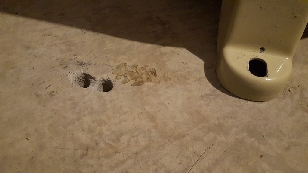
So there it is! The bad! But what to do now? I was worried that using a concrete anchor in the new hole would put enough stress on the errant hole to blow out the small amount of concrete between the 2 holes. After thinking about it, I went to the local home center looking for concrete hole patching or filler. Once there, I must have looked a bit bewildered so one of the guys there came over to see what I was doing. After some discussion, he recommended using another concrete anchor in the errant hole. I thought that since the concrete anchor didn't actually touch all of the sides of the hole, it wouldn't offer enough structural strength. So I ended up settling on the concrete anchor plus super strong epoxy to fill any gaps and hopefully provide some structural strength.
So that's where I'm at right now. I have the new anchor and the epoxy. I have to go measure the exact depth of the hole and then cut off the anchor to the right size. Then its just a matter of mixing the epoxy and putting both down the errant hole. Once the epoxy has dried, I'll feel more comfortable putting the other anchor into the hole and flanging down on it. Once that is done, I can call and schedule the electrician.
Definitely an extra set of steps. All due to a stupid mistake on my part. Thankfully, no one was hurt and nothing was broken. Once its all done and up and running, I'll post a few more pics to show the compete install.
Definitely a bit embarrassing, but that's ok. It's all a part of the restoration adventure!
Tuesday, October 4, 2016
I Am(meter) What I Am
So, another small project to keep me in the game. This project, however, is needed for the restoration, not just because I thought it would be cool. This project started the restoration of the gauge cluster. Some time ago, I found a write up on changing the truck's ammeter to a voltmeter on the Stovebolt.com forum. I thought that the rationale for doing the swap that was included in the write up made good sense, so I decided that I would do it. I read that write up many times over the months, thinking through the process before actually getting the parts ready and starting.
The project itself was actually pretty easy to do. Some of the steps were kind of tedious, but all in all it went pretty quickly. Here's a shot of the gauge cluster and the ammeter before the conversion:

Given the corrosion on the exterior trim ring of the gauge cluster, I was pleasantly surprised to find the inside of the cluster free from corrosion or crud. Now, on to the conversion....
I started with a Bosch voltmeter that I got from my local FLAPS (friendly local auto parts store). It was very inexpensive, costing less than $20. It looked like this out of the box:

The first step in the conversion process is to disassemble the new voltmeter. This involves grinding the edge off the black trim ring. Once that edge is gone, you can remove the front of the trim ring. Then you have to remove the the retaining nuts on the rear of the gauge. Once the nuts are removed, the insides of the gauge can be separated from the case. The disassembled contents look like this:

In this picture, you can see the case, front trim piece, white vibration insulator, actual gauge, electrical insulator from rear of case, lock washers and retaining nuts.
The next step in the conversion is to remove the tiny screws that hold the dial face to the gauge. Jewelers screwdrivers made quick work of removing the screws. A note of caution was provided in the Stovebolt.com write up and is worth repeating here. Those tiny screws go into tiny plastic screw bosses. Over tightening them will break those bosses. Here's a pic of the dial face and screws once they were removed:

I included the jeweler's screwdriver for size reference. Here's a shot of the gauge after dial face removal:

Another note of caution: Notice the thin wire wrapped around the dial face screw bosses? It is a very thin wire and appears that it would be easily damaged. In this pic, I'm test fitting the gauge in the gauge cluster. The gauge would need trimming before it would fit properly. This was expected, based on the Stovebolt.com article. Here are some shots showing why it needed the trim.

Notice the gap between the case and the cluster trim ring?

And on the rear, the gauge's insulators protrude just a little too far and need to be trimmed down a bit. The trimming is a 2 step process where you have to trim both the edge that is visible and the little ledge that keeps the gauge from contacting the cluster mount. That is an awkward description, hopefully this pic, together with the one above will help explain better than I can.

In this shot, you can see the parts of the gauge that keep the actual gauge from contacting the metal of the cluster mount. The other reason that you need to trim these plastic pieces is shown in the next pic. It shows that the needle contacts the cluster trim ring without doing the trimming.

After the trimming, everything fit just fine. It looked like this:

And this:

While it looks like there is still a gap between the case and the trim ring, it isn't because of interference between the gauge and/or needle and the trim.
The next bit of adjustment is to the original gauge face. The original face had 2 dimples punched into it where it was riveted to the original gauge. The gauge face, once removed, looked like this:

and this:

The problem with the dimples was that it interfered with the needle. This is evident from this pic:

Also, the rivet holes were not in the right location for the screws to fit into the new gauge frame. So, I had to flatten the dimples and measure and drill new holes. Once flattened, the gauge face looked like this:

It's a little hard to see, but if you look hard, you can see the black dots where the new holes need to go. I used the new gauge face as a template for locating the holes on the old face plate. One other adjustment to the gauge face that you can kind of see is that the opening that surrounds the needle had to be enlarged. That was done with the Dremel and cut-off wheel. In actuality, the trimming was done before the dimples were flattened. You can see that in this pic, the trimming has been done, but the dimples remain:

Anyway, once all of that was done, I assembled the old gauge face to the new gauge and it looked like this:

The guts from the original gauge are next to the new one. I included the guts from the old gauge to highlight the one real telltale sign of the change. The old gauge reads zero when it's not energized, which is in the middle of the gauge. The new one goes to zero, which is all the way to the left. A subtle difference, but different for sure. We'll see who notes it if I ever get the truck back on the road. Another slight adjustment was painting the needle from the original red, to a more correct white. For this, I just used what I already had on hand, which was Rustoleum flat white.
So, at this point, it looks pretty good...but does it work? Only one way to find out. So, I used some test leads and hooked it up to the engine test stand car battery. It's a normal car battery, connected to a trickle charger. The gauge performed like this:

If you remember from the pic of the original Bosch gauge face, 13 volts is the midway point of that gauge and the zero is the midway point of the original gauge. So, this gauge is reading about 12 volts on my battery connected to the trickle charger. With the engine running, I would expect it to read just above the zero, indicating about 14 volts. Pretty straightforward. Here it is in the original gauge cluster frame:

Here it is connected to the battery, still showing about 12 volts, which shows that the electrical connections are good and separated. Here's a shot of the back, with the insulator in place:

If you enlarge the pic, you can see that Bosch was nice enough to emboss the (+) and (-) on the insulator. Thanks, Bosch! Of course, you do have to orient them in the correct position or the gauge will read backwards!
So that's it! The ammeter is gone, replaced with a voltmeter. The risk of burning my truck to the ground is greatly reduced. Now, I have to address each of the other gauges. I think that I'm going to use a voltage reducer for the gas gauge and retain the original oil pressure gauge. The only wildcard right now is the water temp gauge. I kind of bollixed up that one when I was taking the gauge cluster out of the dash. So I either have to buy an original one and hope that it works or buy a new one. Maybe I'll look into moving the original gauge face onto a newly manufactured gauge. We'll see....
The project itself was actually pretty easy to do. Some of the steps were kind of tedious, but all in all it went pretty quickly. Here's a shot of the gauge cluster and the ammeter before the conversion:

Given the corrosion on the exterior trim ring of the gauge cluster, I was pleasantly surprised to find the inside of the cluster free from corrosion or crud. Now, on to the conversion....
I started with a Bosch voltmeter that I got from my local FLAPS (friendly local auto parts store). It was very inexpensive, costing less than $20. It looked like this out of the box:

The first step in the conversion process is to disassemble the new voltmeter. This involves grinding the edge off the black trim ring. Once that edge is gone, you can remove the front of the trim ring. Then you have to remove the the retaining nuts on the rear of the gauge. Once the nuts are removed, the insides of the gauge can be separated from the case. The disassembled contents look like this:

In this picture, you can see the case, front trim piece, white vibration insulator, actual gauge, electrical insulator from rear of case, lock washers and retaining nuts.
The next step in the conversion is to remove the tiny screws that hold the dial face to the gauge. Jewelers screwdrivers made quick work of removing the screws. A note of caution was provided in the Stovebolt.com write up and is worth repeating here. Those tiny screws go into tiny plastic screw bosses. Over tightening them will break those bosses. Here's a pic of the dial face and screws once they were removed:

I included the jeweler's screwdriver for size reference. Here's a shot of the gauge after dial face removal:

Another note of caution: Notice the thin wire wrapped around the dial face screw bosses? It is a very thin wire and appears that it would be easily damaged. In this pic, I'm test fitting the gauge in the gauge cluster. The gauge would need trimming before it would fit properly. This was expected, based on the Stovebolt.com article. Here are some shots showing why it needed the trim.

Notice the gap between the case and the cluster trim ring?

And on the rear, the gauge's insulators protrude just a little too far and need to be trimmed down a bit. The trimming is a 2 step process where you have to trim both the edge that is visible and the little ledge that keeps the gauge from contacting the cluster mount. That is an awkward description, hopefully this pic, together with the one above will help explain better than I can.

In this shot, you can see the parts of the gauge that keep the actual gauge from contacting the metal of the cluster mount. The other reason that you need to trim these plastic pieces is shown in the next pic. It shows that the needle contacts the cluster trim ring without doing the trimming.

After the trimming, everything fit just fine. It looked like this:

And this:

While it looks like there is still a gap between the case and the trim ring, it isn't because of interference between the gauge and/or needle and the trim.
The next bit of adjustment is to the original gauge face. The original face had 2 dimples punched into it where it was riveted to the original gauge. The gauge face, once removed, looked like this:

and this:

The problem with the dimples was that it interfered with the needle. This is evident from this pic:

Also, the rivet holes were not in the right location for the screws to fit into the new gauge frame. So, I had to flatten the dimples and measure and drill new holes. Once flattened, the gauge face looked like this:

It's a little hard to see, but if you look hard, you can see the black dots where the new holes need to go. I used the new gauge face as a template for locating the holes on the old face plate. One other adjustment to the gauge face that you can kind of see is that the opening that surrounds the needle had to be enlarged. That was done with the Dremel and cut-off wheel. In actuality, the trimming was done before the dimples were flattened. You can see that in this pic, the trimming has been done, but the dimples remain:

Anyway, once all of that was done, I assembled the old gauge face to the new gauge and it looked like this:

The guts from the original gauge are next to the new one. I included the guts from the old gauge to highlight the one real telltale sign of the change. The old gauge reads zero when it's not energized, which is in the middle of the gauge. The new one goes to zero, which is all the way to the left. A subtle difference, but different for sure. We'll see who notes it if I ever get the truck back on the road. Another slight adjustment was painting the needle from the original red, to a more correct white. For this, I just used what I already had on hand, which was Rustoleum flat white.
So, at this point, it looks pretty good...but does it work? Only one way to find out. So, I used some test leads and hooked it up to the engine test stand car battery. It's a normal car battery, connected to a trickle charger. The gauge performed like this:

If you remember from the pic of the original Bosch gauge face, 13 volts is the midway point of that gauge and the zero is the midway point of the original gauge. So, this gauge is reading about 12 volts on my battery connected to the trickle charger. With the engine running, I would expect it to read just above the zero, indicating about 14 volts. Pretty straightforward. Here it is in the original gauge cluster frame:

Here it is connected to the battery, still showing about 12 volts, which shows that the electrical connections are good and separated. Here's a shot of the back, with the insulator in place:

If you enlarge the pic, you can see that Bosch was nice enough to emboss the (+) and (-) on the insulator. Thanks, Bosch! Of course, you do have to orient them in the correct position or the gauge will read backwards!
So that's it! The ammeter is gone, replaced with a voltmeter. The risk of burning my truck to the ground is greatly reduced. Now, I have to address each of the other gauges. I think that I'm going to use a voltage reducer for the gas gauge and retain the original oil pressure gauge. The only wildcard right now is the water temp gauge. I kind of bollixed up that one when I was taking the gauge cluster out of the dash. So I either have to buy an original one and hope that it works or buy a new one. Maybe I'll look into moving the original gauge face onto a newly manufactured gauge. We'll see....
Subscribe to:
Posts (Atom)