1953 chevy truck ad

1953 chevy truck ad

Sunday, February 24, 2019

Splitting Up (A Universal Joint) is Hard to do

Hello Gray Ghost Fans!

It's still cold outside, but things are heating up in the garage!  And by heating up, I mean getting serious!  It was time to overcome my fear of the torque tube crushing my skull and get to work on splitting the universal joint.  This has to be done in order to get the transmission out, which is the next major step in the engine swap process.  Friday was a regular day off, so out to the garage I went!

Now, in the spirit of full disclosure, I had already loosened the bolts that held the universal joint cover collar in place and unscrewed the u joint cover end cap and slid it to the rearmost position on the torque tube that it can go.  However, on this first attempt, the u joint cover would not budge.  I could not rotate it, slide it or wiggle it out from it's position.  I made a request of my forum buddies and the awesome suggestion of using a strap wrench came back.  A quick trip to the big box store and I was the proud new owner of a strap wrench.

After clearing out the garage, I got under the truck and attached the strap wrench.  At this point, it was just silly how easy it was to rotate the u joint cover.  Once again, the lesson of leverage was taught.  With the u joint cover now moveable, it easily slid down the torque tube and out of the way.  Here is the assembly prior to moving the collar rearward:


In this shot you can see a block of wood.  This is a good time to let everyone know that the torque tube is under pressure from the rear axle, so using a floor jack is required to ensure safety.  The whole thing looked like this:


I know, even to me it looks a little dodgy.  But the truck was on jack stands and pretty high off of the  ground.  So the floor jack wouldn't reach without the wood block.  Thankfully it held.  Time for that u joint.

With the torque tube supported, there was no pressure on the u joint, so it was just a matter of finding the right wrenches and unbolting some unnervingly small bolts.  I noticed as I was working on the bolts that they really weren't torqued down very much, although they did still have the safety tabs in place that prevent them from spinning loose.  Only one of the four bolts had a washer and one of the four bolts was a different size bolt head, but same size shaft and threads.  It was odd.

Now I was able to slide the torque tube side of the u joint backward, too.  Using the floor jack, I raised the torque tube as high as it would go and installed a 2x4 cut to fit between the frame rails.  Once that was in place, I lowered the torque tube until it rested on the 2x4.  It was now safely out of the way.  That means it was time to start on that transmission.

First on the agenda was to undo the shift rod linkages on the side of the transmission.  That was easy as the rods are held to the transmission with a washer, spring and cotter pin.  With the exception that one of the cotter pins was really hard to get to, this part of the job wasn't bad.

Next, it was time to make a tool.  This required cutting the head off of 2 bolts that will act as guide pins for removing the transmission.  This is what it looked like:


Before
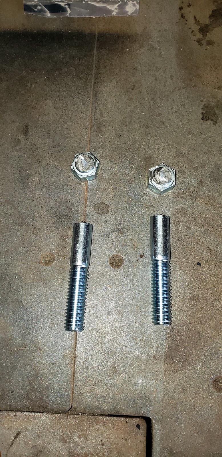

After

Once again, not too mentally taxing.  The shop manual for the truck tells you to remove the two top bolts and insert Chevrolet guide pins J-1116.  Those are antiques and not readily available, so making your own out of these bolts is the next best thing.

With the guide pins made and installed, it's time to get the bottom two bolts out.  The top bolts attach the transmission to the clutch cover (bellhousing).  The bottom two bolts attach the clutch cover to the transmission.  They go from inside the clutch cover into the threads cut into the transmission.  On the top, the transmission only has holes and the clutch cover has threaded holes.  Not sure why they did it that way, but ok.  You creep a little farther under the assembly reach into the clutch cover and a 3/4" wrench makes quick work of them.  Once again, not much torque on those bolts....

With the bolts out and the guide pins in place, it's time to slide the transmission out.  The guide pins keep the input shaft of the transmission from damaging the clutch while it slides out.  At least that's what the manual says that they do.  I wouldn't know, because having the torque tube raised all the way up blocks the space that the rear of the transmission needs in order for the input shaft to clear the clutch cover!  OY!  I knew that this was going to smoothly!

So...I reached out to my forum buddies again and learned a couple of things.  Most important, having the jack stands on the rear axle (like I did) puts all the weight of the truck onto the axle and consequently onto the torque tube.  If the 2x4 were to fail to hold the tube, it would crash down with considerable force and could actually be lethal.  Time to take a step back and rearrange the jack stands.  Saturday was a washout, which meant that I couldn't clean out the garage to get access to the underside of the truck.  It would have to wait.  Sunday started with rain, but cleared by mid-morning.  Time to get back to work!

It was a total PITA to move the jack stands!  Let's just say that it is done.  In the process, I lost several inches of clearance, which means that working under there will be that much more difficult.  By the time that I got done with the jack stands I was pretty tired (it's a really long story).  After that ordeal, I spent some time cleaning grunge off of the replacement engine.  Not fun nor pretty work, but useful.  Next weekend I'll go after the transmission one more time.  This time, I plan to lower the torque tube out of the way, making the room I need to get the transmission out.  Once the transmission is out, I'll raise the torque tube again and block it with the 2x4.  Assuming that I can do that, the only things left to do are to remove the 2nd and 3rd gear shift rods from the clutch cover, drain the oil and remove the hood.  It will then be time for removal of the dead engine!  Like I said, things are heating up!  Stay tuned for more Gray Ghost action!

Monday, February 18, 2019

Three Days of Pain, But at Least I Can Sit Now

Hello Gray Ghost Fans!

I'm sure you're wondering about the title of the post.  Is it risque?  Absolutely not!  All will be revealed in due time.  But first, a quick pictorial reminder of where we started:


Yeah, Baby!  Nothing like a visual reminder of how she got her name!  Anyway, so what's going on?  Upholstery, that's what's going on!  The floral print sheet was nice and all, but it did smell of mouse pee and was probably 30 years old.  So when I did the cab cleaning, the sheet, 2 layers of seat covering material and all of the old padding went into the trash.  The seat cushion springs were treated to a good power washing and set in the sun to dry.  Afterward, I just put down a sheet of plastic and an old strip of carpeting to sit on while I did other work in the truck.  In the meantime, I acquired the seat coverings but never got around to doing the reupholstering.  This winter, I got the seat cover installation kit and was out of excuses.  After doing a little research, it was off to the races.

You start with the bare seat cushion frame.  I sprayed it with the Rustoleum rust converter.  After it was dry, I brought it into the basement for a warm place to work.  The frame looked like this:


To the frame, I used hog rings and attached a carpet runner that I cut to match the outline of the frame top.  That looked like this:


The purpose of the carpet runner is twofold.  First, it provides some isolation from the seat frame springs and your butt.  Second, since it has a rubber backing, it keeps the springs from contacting material that may absorb moisture and cause more rusting.  Anyway, it is Home Depot, buy it by the foot carpet runner.  Next comes a layer of burlap.  It looked like this:


Originally, the burlap helped keep the cotton batting in place and from dropping down into the springs.  In this application, it isn't really necessary, as the carpet runner does that job, but the kit contained it, so I used it.  Next is the cotton batting.  The instructions that came with the kit said that I should use at least 2 layers.  The kit came with enough to go down, back and down again.  So I got 3 layers.  The cotton batting looked like this:


I left the cotton batting long on all sides, as I wasn't sure how the seat cover material would interact with the batting.  I figured that I could trim it as I was fastening the seat cover to the frame, which is exactly what I ended up doing.  So, next comes the seat cover material:


All you have to do at this point is fold over the edges and begin the process of fitting the edges of the seat cushion frame into the seam areas of the seat cover material.  Not hard, but a little tedious.  Next comes permanently attaching the material to the frame.  The kit came with what's called "C" clips.    The instructions that came with the kit were a little nebulous, stating:  "Press special "C" shape clips at rear of springs to permanently hold cover in place."  This, sports fans, is where the pain begins....

Not knowing what this meant, I literally spent some time staring at the underside of the seat frame.  I mean, hey, I'm a product of the Prince George's County school system with a degree from an institution of higher learning.  How hard can this be?!?  Answer, pretty hard.  Enough time wasted, let's call the vendor and ask for technical help.  OY!  Are you kidding me?  While good intentioned, the tech actually googled my question while I was on the phone and pointed me to a Youtube video that I already knew about!  When confronted with that, he deferred to another technician and needed to call me back, which he did in a few minutes.  The "expert" told me to do something, that I can no longer remember, it was that off the wall.  So, getting no help from the vendor, I reached out to the members of the truck forum that I belong to.  Most people there told be to wrap the seat cover material over the bottom of the frame and use the clip to hold the material to the frame.  This is what I was thinking that the clip was for, but there was a small problem.  I'll illustrate the problem with a pic:


Between the frame and material, that's 1/2" of thickness with a clip that is 1/8" at the opening and 1/4" at the widest part inside.  There was no way that clip would ever fit over that material and likely would tear it if I tried. 

Originally, Chevrolet used what look like "V" clips.  The shape of the frame is like a "J" with the hook of the J facing the inside of the frame.  They used the V clips to hold the material inside the frame.  Those clips, inside the frame looked like this:


In many instances, there were 2 clips nested inside of each other.  I think the assembly people got slap happy and just grabbed a bunch and kept on going.

So, after much trial and error.  After much ado trying to figure out how to make the clips fit over the frame, I said to heck with this.  I'm going to do it the way the Chevrolet did it.  The C clips are going into the frame.  I thought that this was doable because of the similar size of the clips, shown here:


Original V clip on the left and new C clip on the right.  However, before I could do that, I had another restoration challenge to get over.  Once again, a picture is worth a thousand words:


Yep, I never intended to clean out the hook part of the frame, as I never intended to use it!  Crap!  That meant disassembling what I had already put together and taking the frames outside to get that dirty mess out.  I guess I should have done this initially, and I did try.  But at the time, I had no idea how the fabric was held in place.  It took me 2 different sessions over 2 different days to get this cleaned out and repainted.  It hurt my hands so much they were useless the rest of the day.  First you have to pry the clips from the edge, then bend them so that they can come out and then finally grab them with 90 degree needle nose pliers and forcefully wrangle them out.  Then you can work on the material, which after 65 years, has solidified into something akin to tile.  Tile that is in the shape of the J hook!  Very tedious, very fiddly as getting a straight in angle was impossible and very painful to my old joints.

The first installation of a C clip looked like this:


It turns out that getting the first clip installed on a new side is the hardest part.  Once you have 1 clip installed, it helps hold the fabric so that you can make the bend on the next spot and so on.  Here's a shot of one side completed:


Even with clips installed, spring clips are your best friend here.  One is visible to the left.  The corners proved to be a bit tricky, too. but manageable if you go slow.  The seat bottom cushion looked like this when done:


Here, it is sitting on the basement floor.  There are still some folds visible in the material and the instructions say that they will go away soon after installation.  In it's defense, the material did sit in a box at my house for nearly 3 years.  So the creases weren't unexpected.  The seat bottom cushion also got an extra layer of a really dense felt.  The felt came in the installation kit and provides for a little creature comfort when driving around in your truck.

Now it's time for the big reveal.  How do they look in the truck?!?  Well, let's see:


Hey now!  Not too shabby!  Remember, the goal of the interior work is to make the cab livable while I work on other things.  Recovering the seats will not be wasted, if I decide to do a frame off restoration in the future.  At that point, I'd just take the seats as they are and store them for reinstallation when needed.  Same for the new gauges.  The rattle can paint is just for me.  And so are the seats.  I now have a proper place to sit.  And now the title is revealed.  It was a painful process that lasted over 3 days, but resulted in a nice place to sit.

That's all for now.  My next focus is on the engine.  I'm going to need advice and maybe actual help.  So I'm off to contact my forum buddies.  I've got questions.  Lot's of questions.


Just in case anyone was wondering.  Yes it hurt, but it did make me happy.

Sunday, January 27, 2019

Making The Go Pedal Go

Hello Gray Ghost Fans!

Well, it's mid-winter and you know what that means.  Time for small projects to try and keep things moving forward while we wait for the warmer weather.  Now, these aren't time wasters, these are things that need to be done, but are always lower on the list.

One of those projects is to either adjust or make a new connecting rod that goes between the gas pedal and the engine block.  This rod is a part of the overall linkage system that controls speed through the carburetor.  The reason for having to do this is that the replacement engine block that I have only has one mounting point for the pivot (also a part of the overall linkage) and it is in a different place on the block than the engine that I am removing.  The mounting point for the pivot is about 3" closer to the firewall than the original engine.  That means that I could shorten the original rod or make a new one.  I chose to try and make a new one, so that I could preserve the original one.  Whenever possible, I try to keep original parts intact, even if I choose to use new parts.  The original rod and the proposed replacement look like this:


The original rod is in the top of the pic.  The ball at the top is what mounts to the back of the gas pedal.  You can see that the top portion of the rod is thicker than the bottom portion.  The bottom portion is 3/8" diameter.  The drawing below the rod is an outline of the rod's shape with hash marks added every 1/4".  I transferred the hash marks to the new rod, which is 3/8" the entire length.  The round part on top of the rod is a gas strut mounting ball that I bought for this purpose.  It came in metric sizes, but the ball measured the same as the original ball.  To make it fit, I got out the old tap and die set and added M6-1.0 threads to the rod.  Piece of cake, by now.

The thought is to put the rod into the bench vise, which is almost closed around the rod and make small bends at each hash mark.  The cumulative effect of many small bends is hoped to replicate the sweeping curve of the original rod.  To easily bend the 3/8" steel rod, I used a piece of iron pipe slipped over the steel rod..."give me a big enough lever and I can move the world"...works!  At any rate, the first pass through the process resulted in this:


Holy Cow!  This might actually work!  Time for a second pass.  It resulted in this:


OK, progress, but slow.  And that's alright!  I only want to do this once!  Time for a third pass.  That resulted in this:


Almost there.  One more time!  That resulted in this:


TaDa!  That is pretty darn close.  But wait, the end of the rod isn't quite at the same angle as the original after all that bending.  Will it even fit and be close to the linkage?  Time for a test fit....  It looked like this:


Here we can see the new rod coming through the firewall, after I attached it to the gas pedal.  The rod is resting on top of the fitting for the oil pressure gauge and remote oil filter.  The pivot mounting point is center frame and the rod goes right past it.  That means that it is plenty long enough and actually will work!  A side view of the rod, in position with the current pivot mounting point looks like this:


Remember, the new engine has the mounting point about 3" closer to the firewall.  That means that the new rod is way longer than it needs to be.  But, to void screwing it up now, I'm going to leave the rod as is, until the replacement engine is in the truck.  Then I'll measure exactly where the rod needs to be bent to fit the new engine.  Once bent, a quick trim of the rod to the correct length and drilling a small hole in the end for a cotter pin will be all that's needed.  At that time, I'll also add some thread locker to the rod and permanently mount the ball end to the rod.

Not too shabby, I'd say.  I guess the jury will be out until I actually use the new rod to work the accelerator.  The only concern that I have is the use of a 3/8" rod for the entire length and not doing what GM did and use two different thicknesses.  Truthfully, I don't see the rod bending, but if it does, I can always go back to the original rod and make it fit the new engine.

That's all for now.  Here's looking forward to some warmer weather!

Wednesday, January 9, 2019

Gray Ghost Heater Decalcomania

Hello Gray Ghost Fans!

It's been a long time since my last post.  In fact, a little too long.  However, I do have my reasons...like being busy on an important woodworking project for my family.  So while it's a departure from the Gray Ghost, here's a shot of the project:


It's a dresser!  A purpose built, built to fit the space dresser.  It stands about 51" tall and 48" wide and allows for some better organization.  It is built in the old crate furniture style, so that it matches the beds that were already in the room.  Family will always come first, so when the need was identified, I got on it.

Time passes and it is then onto the Christmas season!  My big present from my wife to me was a new heater core from a company called Brassworks!  It looks like this:


It is designed to be a drop in replacement for the old style, hard to repair round heater core found in my truck.  So once the holidays were over, I was free to start work on the restoration of the truck's heater.

Now, to level set the task, here's a shot of the heater, as it sat in the truck on the day that I got it:


An interesting side note about this heater:  based on the Chevrolet decal, this is a 1954 model heater.  It is totally possible that the original owner added the heater after the new model year started, resulting in a 1954 model year heater going into a 1953 truck.  And yes, heaters were optional equipment!

Anyway, it looks pretty rough, but just how rough?  Here are the pics of the heater after I got it out of the truck:


You can see the worst of it is the bracket that holds the heater core inside the heater box.  Of course it's the worst!  I only have to reuse the bracket and the box, why shouldn't they be rough.  In fact, the bracket was bad enough that I decided to use a different one that I had already salvaged from the junkyard a couple years ago.

The first step in the process is to separate the bracket from the old core.  To do this, you have to de-solder it.  My micro torch wasn't up to the task, so I went out and got a MAP gas torch, which made quick work of it!  After separating the two parts, I had to clean all of the old solder off of the bracket.  The process looked like this:


After cleaning the solder, it looked like this:


Clearly, even this bracket would need some blasting, so when I got a warm day, that's what I would do:  blast everything that needed it.

Well, I finally got my warm day, which meant it was time to disassemble the old heater box and all of its' components so that they could be blasted.  Here's how it all looked after blasting:


A whole lot better, but....  Clearly there is still some pitting that I can't seem to get clean.  I'm guessing that the sandblasting grit was too large to get down into those spots.  So, I spent some quality time with various grits of sandpaper, working on specific spots.  Still, there would be some pitting that I just couldn't get, for fear of taking out too much metal.  Time for an experiment!  Since the majority of the rust was actually gone, I thought I'd try the Rustoleum brand rust encapsulator to see how it would work.

So off to prime my newly cleaned, 65 year old parts!  Let me just say wow to the Rustoleum rust encapsulator!  I have no idea if it will work to keep the rust from reappearing, but what an awesome primer!  My primed parts came out like this:


Yes, some of the really bad pitting is still visible, but I couldn't have been happier with the priming results!

Now that the metal is protected, I had a little fitting work to do to mate the old bracket to the new heater core.  This entailed drilling 4 holes into the heater core flanges, avoiding the heater core tanks (it is made like a mini radiator with tanks on either side).  I used #6-32 x 1/2" nuts and bolts (with lock washers) to secure the bracket to the heater core.  Once I was happy with the holes, I painted the bracket a satin black.

Now the $64 question:  what color to paint the heater box and air diverter part?  The original pic isn't much help:


But...maybe there was a clue under that 65 year old decal...


Holy crap!  It's actually hammertone silver!  That can't be, let's check for another protected area and see if that is real!


Look closely at the right side of the heater box and the heater hose connection points.  Hammertone silver!  Well alright, hammertone silver it is!

Laying down a coat of that paint on top of that awesome primer was easy!  Getting the hammertone effect was a little harder.  After using it, I think that the key to the hammertone effect is to lay down a thicker coat of paint than you would normally lay down.  That would be fine, if the parts weren't hung on a rack for spraying....  Anyway, the silver looks great:


Here you can see all of the parts that will be assembled into the heater box, minus the heater core assembly.  Assembling the control rod with washers and spring into the box and onto the diverter was a bit fiddly, but I eventually got it without breaking anything!  The key to this was taking a pic of the assembly before disassembling it!  Before and after:


Obviously, in the first pic I've already removed the diverter.  But I had the sense to get a photo of the parts in the correct order and placement before removing them!  Getting the diverter wedged between the washers and spring was a challenge, but it is manageable.  Onto assembling the heater core and bracket.  This was easy, as I'd already done it before painting.  Once done, it looked like this:


In the bottom pic you can see that I wedged in a round grommet into a rectangular hole.  I felt like it needed something, so I winged it and got a larger Grommet from the store and it mostly fits.  In these pics you can see the #6 nuts and bolts.

On to the Decalcomania!  Normally I would look to the Factory Assembly Manual (FAM) for the drawing that showed exactly how and where to place the decal.  However, since the heater is a dealer installed option, it isn't in the FAM.  It's in the accessory installation manual.  A manual that I don't have!  Looking at the original decal and a photo from an online accessory installation manual, it appeared as though the writing was supposed to be parallel to the square shape embossed into the heater box.  That way, when the heater was installed into the truck, it would be rotated into a jaunty angle.  Anyway, here's how mine now looks:


Quite the transformation!  I'll keep this out of the truck until after I do the engine swap.  I figure having those tubes from the heater core sticking out into the engine bay would just be an invitation to damage the new core.

The knob on the control rod is original to the heater.  It is still kind of dingy looking and it has a couple of large cracks in it, but they don't make them anymore so I'm sticking with it for now.  If it breaks, I have a NOS replacement, but it too has cracks.  Also, visible in the above pics are the two wires for powering the fan.  They came installed in a non-standard connector and looked like this:


I depopulated the nonstandard connector and will purchase both sides (male and female) of a standard connector.  It's all a part of the process.

That's all for now.  Happy New Year, Gray Ghost Fans!