Gray Ghost fans, I have very bad news.... The greedy people at photobucket have eliminated viewing of all free account photos that are linked in 3rd party sites. Like this one. Recently, I had been hosting new Gray Ghost photos on Google photos, but I have over 600 photos on photobucket with most used in earlier posts. All of the videos in the sidebar are on photobucket. So, if you try to view an old post and get the error image about me updating my account to a pay account, I apologize. I will eventually migrate all of the photos to Google and reestablish the links, but that will be a big undertaking and will take months.
To say that I am upset by this is an understatement, but just like any other setback when working on the Gray Ghost, I'll persevere. It'll just take a while.
1953 chevy truck ad

Friday, July 14, 2017
Monday, July 3, 2017
HOT : Wiring Progress Update
It's July 3rd, which means its hot and humid out there today. I spent the morning out in the garage working as best as I could. Currently, it is 92 degrees with a feels like temp of 100. The sun was shining into the garage this morning, so there wasn't any break from the heat. I managed about 3 hours out there before I just had to take a brake. In that time, I did make some progress. For example, I permanently mounted the fuse block onto the interior of the firewall. The before and after looks like this:

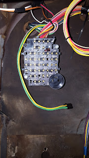
It's a bit of apples to oranges comparison with the wide shot vs close up shot, but you can tell that the clutter from the first shot is gone. So what happened? First off, as I mentioned in my last post, I rotated the fuse block 180 degrees. This put the wires exiting the block toward the openings in the firewall and up under the dash, so that the remaining interior wires could be directly routed towards the gauges, ignition switch and heater. That, all by itself, cleaned things up. Getting the additional wire for the bundles that go through the firewall actually through it also helped clean things up. To actually mount the fuse block to the firewall, it was recommended to me that I build standoffs to elevate the fuse block off of the old firewall padding. I did this by buying a 4 1/2" x 1/4" hex head bolt, some fender washers, nuts and lock nuts. What I did was insert the hex head bolt through the firewall from the engine compartment into the cab and attached 7 nuts to the bolt. This gave the fuse block just over an inch in clearance between the back of the block and the firewall padding. It was capped off with a lock nut so it won't vibrate loose. The above pic is a nice shot of the fuse block without any fuses installed yet. The yellow and green wires hanging down are for the dimmer switch. It will be mounted over the hole that is visible in the bottom of the above pic. The old dimmer switch mounted through the firewall, but the new one sits on top of it. So, I'll have to cover that hole up somehow.
Inside the engine compartment, I separated the wire bundle into groups. One group goes across the compartment to the passenger side, while another group stays on the driver side and a third group goes directly to the engine. The third group is made up of engine sensor connections like water temp, oil pressure and tach. They'll be tucked out of the way until after the engine swap is completed. The wires that were routed to the passenger side include the headlight wires (both high and low beam), right turn signal, ignition switch to starter and wipers. They were all encased in the split wire loom and routed across the firewall using factory clips. At this point, I've run out of the split wire loom and will have to buy some more. This time,though, I'll get 1 size smaller as I have fewer wires to encase on the driver's side. All in all it's starting to get organized and looks like this:


Before

After

It's a bit of apples to oranges comparison with the wide shot vs close up shot, but you can tell that the clutter from the first shot is gone. So what happened? First off, as I mentioned in my last post, I rotated the fuse block 180 degrees. This put the wires exiting the block toward the openings in the firewall and up under the dash, so that the remaining interior wires could be directly routed towards the gauges, ignition switch and heater. That, all by itself, cleaned things up. Getting the additional wire for the bundles that go through the firewall actually through it also helped clean things up. To actually mount the fuse block to the firewall, it was recommended to me that I build standoffs to elevate the fuse block off of the old firewall padding. I did this by buying a 4 1/2" x 1/4" hex head bolt, some fender washers, nuts and lock nuts. What I did was insert the hex head bolt through the firewall from the engine compartment into the cab and attached 7 nuts to the bolt. This gave the fuse block just over an inch in clearance between the back of the block and the firewall padding. It was capped off with a lock nut so it won't vibrate loose. The above pic is a nice shot of the fuse block without any fuses installed yet. The yellow and green wires hanging down are for the dimmer switch. It will be mounted over the hole that is visible in the bottom of the above pic. The old dimmer switch mounted through the firewall, but the new one sits on top of it. So, I'll have to cover that hole up somehow.
Inside the engine compartment, I separated the wire bundle into groups. One group goes across the compartment to the passenger side, while another group stays on the driver side and a third group goes directly to the engine. The third group is made up of engine sensor connections like water temp, oil pressure and tach. They'll be tucked out of the way until after the engine swap is completed. The wires that were routed to the passenger side include the headlight wires (both high and low beam), right turn signal, ignition switch to starter and wipers. They were all encased in the split wire loom and routed across the firewall using factory clips. At this point, I've run out of the split wire loom and will have to buy some more. This time,though, I'll get 1 size smaller as I have fewer wires to encase on the driver's side. All in all it's starting to get organized and looks like this:
Before

After

The wires splitting off of the center bundle are brake light wires and go to the brake light switch which is mounted to the engine side of the firewall. These include the third brake light, which I'm going to use. I have a special plan for the third brake light assembly, but that is a surprise for a later post! The rest of that bundle includes all of the "rear of the truck" wires. The blue and brown wires splitting off from the rightmost bundle include the left turn signal and park light. All of the other wires on the right are for the engine sensors and tach. I will likely route those under the other wires that cross over the firewall in a separate loom and take them straight to the engine. Another thing that is visible here are the hex bolts and fender washers. I was able to reuse one of the existing holes in the firewall to mount the fuse block. However, I did have to drill a second one to match the mounting hole pattern.
It's a truism that nothing just bolts right up, even if its supposed to! The most recent case in point is the headlight switch. The new switch is designed to work exactly and even had the anti-rotation tab in the right spot. Held up to the inside of the dash it looked like this:

You can notice the square tab to the side of the hole. The switch has a tab that fits in that square part and keeps the whole thing from rotating when you turn the knob to activate the dome light. The problem was that the decorative nut that goes through the hole and screws onto the switch had a gap when fully seated. This meant that the switch flopped around in the opening. The gap looked like this:

To solve the problem, I got a large washer to fill the space. But since it would be on the outside of the dash, it would be visible. That would look kinda tacky having a nice painted dash and a grade 8 washer for all to see. The solution was to paint the washer. You know I love my pics so here goes:

Nice transformation from the normal look of a grade 8 item to a nice Gray Ghost painted dark bronze! I'm still waiting for the paint to fully cure and harden. It's so hot out there in the garage that I'll probably be able to put it on tomorrow without scratching any of it.
Also today, the mailman brought a couple of special deliveries! I had ruined the original cylinder lock trying to get it out of the original ignition switch. So a new one was in order. It came today and with a little figuring, I was able to get it into the new ignition switch. So that part is now ready to be connected to the new wire harness and installed into the dash. Those wires already have been terminated and have the female end for spade connectors which fit onto the new switch.
Another item that came in that package were the Chevrolet letter decals for the dash trim. I figured that since I was already placing an order, why not get them. I've been wanting to finish off that piece of the trim for months, but had no reason to place an order. So I just waited. Once they got here, it was short work to get them on. Before and after looked like this:
Before

After

Other than the flash washing out the center, they aren't too shabby. Although, to be honest, they are 10 foot decals, not 10x magnification decals as they don't exactly fit into the stock spaces. But for my purposes I was pretty happy. Now back down to the basement for that piece until I'm finally ready for it!
That's all for now. Happy 4th of July, Everyone! Happy Birthday, America!
Saturday, July 1, 2017
Old Grommets and New Wires
Yesterday was a big day in the garage, Gray Ghost fans! It marked the beginning of the new wire harness installation. In preparing for the installation, I read and reread the installation instructions and tried to match up as much of the wiring and associated hardware as possible. Here is the stuff before I spread it out as I prepped:

What I have is a Speedway Motors universal wire harness, Rebel Wiring headlight relay and a period correct turn signal switch. Also visible are the wire harnesses and sensor connectors for my New Vintage gauges! A sharp eye will also catch the LED flashers in the box. I have to switch to those because I'm using LED bulbs in the turn signals and tail lights.
I had already decided that I would route all of the wires using the factory locations. That helped me locate where I had to place the new fuse holder. I ended up using one of the old fuse holder holes and drilling out the second hole for the other attaching bolt. However, prior to attaching the fuse holder, I had a lot of wires to pull through those grommets. Inside the engine compartment, it looked like this:

On the right, you can see most of the engine compartment wires. There are still a couple of engine related wires to install, but they will likely wait until after the engine swap is done. The engine compartment wires include headlight wires, ignition wires and brake light wires. The wires on the left are rear of the truck wires and include tail light wires and third brake light wires. I ran them in some split wire loom, to protect them, through the factory locations.
Inside the cab, the wires are just kinda roughed in at the moment. It currently looks like this:

Since this photo was taken, I've decided to rotate the fuse block. It made more sense to put it that way, since it put the wires exiting the fuse block pointing towards the firewall holes. It also gave me some more slack on the dome light wires. Yesterday, when I ran those wires, they came up a bit short of the required location. It looked like this:

In this pic you can see that I used the old wire as fish tape and was able to pull the new wires up from the under dash area, through the A pillar and to the channel above the door and to the rear of the truck. That is the factory routing. Even with the extra slack, I think I'll be a bit short and will have to extend them. So far, that is the only issue that I've encountered with the Speedway harness. Overall, I've been very impressed with the harness. The wire colors follow the GM convention and are labeled every foot or so. The instruction sheets are pretty thorough and easy to follow. Now, the aftermarket turn signal switch was another story.... Those instructions left a little to be desired. I think I've got it figured out, but I won't know for sure until I put power to the new system. That is some time away.
Next on the agenda is to get the wires into their final, factory locations and to make each of the wire connections. That will probably take some time as I want to take my time and do it right.

What I have is a Speedway Motors universal wire harness, Rebel Wiring headlight relay and a period correct turn signal switch. Also visible are the wire harnesses and sensor connectors for my New Vintage gauges! A sharp eye will also catch the LED flashers in the box. I have to switch to those because I'm using LED bulbs in the turn signals and tail lights.
I had already decided that I would route all of the wires using the factory locations. That helped me locate where I had to place the new fuse holder. I ended up using one of the old fuse holder holes and drilling out the second hole for the other attaching bolt. However, prior to attaching the fuse holder, I had a lot of wires to pull through those grommets. Inside the engine compartment, it looked like this:

Inside the cab, the wires are just kinda roughed in at the moment. It currently looks like this:

Since this photo was taken, I've decided to rotate the fuse block. It made more sense to put it that way, since it put the wires exiting the fuse block pointing towards the firewall holes. It also gave me some more slack on the dome light wires. Yesterday, when I ran those wires, they came up a bit short of the required location. It looked like this:

In this pic you can see that I used the old wire as fish tape and was able to pull the new wires up from the under dash area, through the A pillar and to the channel above the door and to the rear of the truck. That is the factory routing. Even with the extra slack, I think I'll be a bit short and will have to extend them. So far, that is the only issue that I've encountered with the Speedway harness. Overall, I've been very impressed with the harness. The wire colors follow the GM convention and are labeled every foot or so. The instruction sheets are pretty thorough and easy to follow. Now, the aftermarket turn signal switch was another story.... Those instructions left a little to be desired. I think I've got it figured out, but I won't know for sure until I put power to the new system. That is some time away.
Next on the agenda is to get the wires into their final, factory locations and to make each of the wire connections. That will probably take some time as I want to take my time and do it right.
Subscribe to:
Posts (Atom)