1953 chevy truck ad

1953 chevy truck ad

Thursday, November 26, 2015

B-31 ! But Not BINGO!

As I mentioned in my last post, I wanted to do the rewiring / restoration of the remaining backup light (the Guide Lamp Company B-31) this weekend.  Before I got to the light, I had an idea of making a bracket similar to ones that I had seen on eBay for these backup lights.  They looked pretty straightforward, essentially just an L shaped piece of flat steel with a smaller flat steel piece that went on the opposite side of the bumper bracket.  They were held together with small bolts and nuts.  Like I said seemed pretty straightforward.  But the reality was not so much.  I got the flat stock, made the measurements and made my first bend.  So far so good.  But when I got it to the truck, I realized that the geometry of the bumper brackets (not right angles to the bumper) would require something that would pivot.  I had seen those, too, on eBay, but didn't want to spend the money to get them.  Guess what...I'll be getting them.  After making a valiant attempt at making my original idea work, I had to give up.  Wasn't going to happen.  So I'll be saving my money to buy the brackets online.  In the meantime, I went back to the B-31.

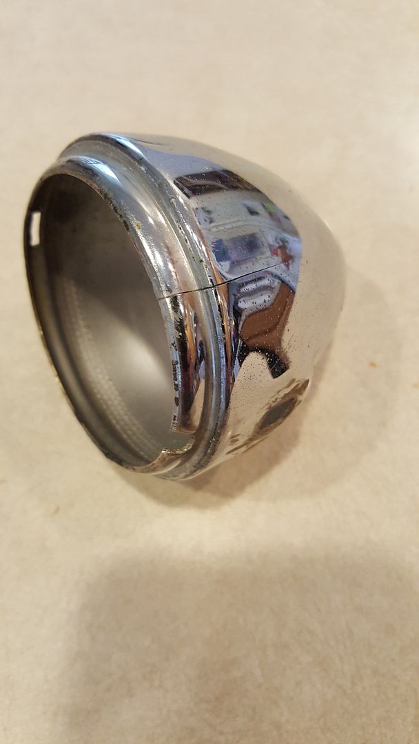
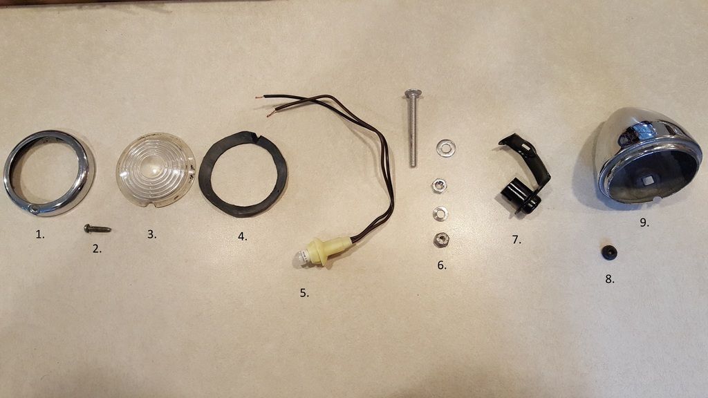
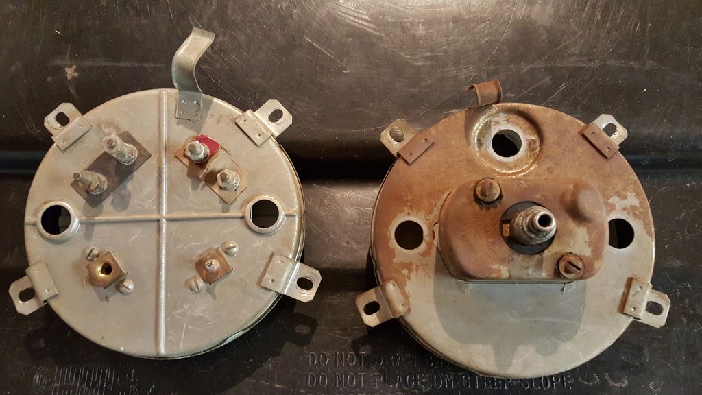
Disassembly was easy and the major parts looked like this when apart:
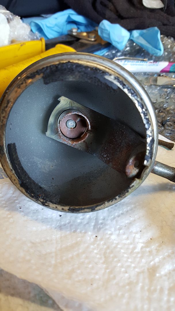

and this:


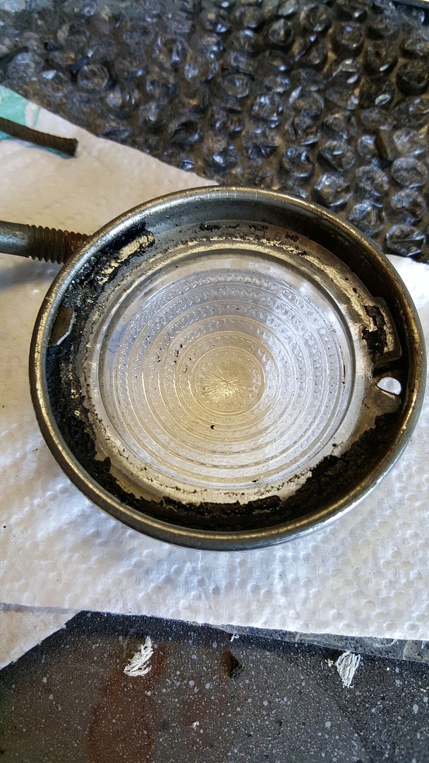
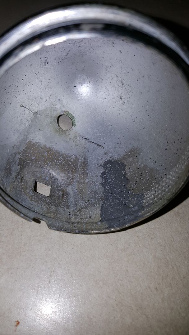
The black gunk in both pics are the remnants of the original gasket.  Not sure what they made it out of, but it came out in big hunks.  What remained came out with Formula 409 on a paper towel and some wiping.

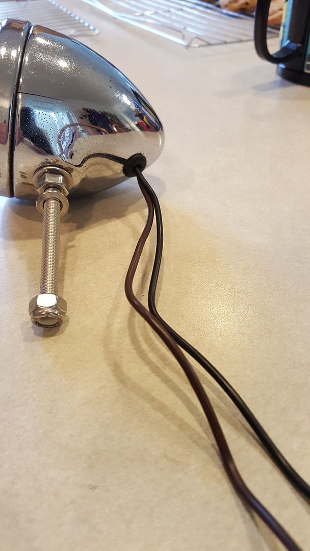
You'll notice some rusting on the bulb housing, just like in the previous light.  The difference here, is that this light still has the original carriage bolt attached and it is press fit into the housing.  So it wasn't going to go anywhere.  That meant that I would have to remove the rust with the bulb housing still attached to the light housing or body.  That made things difficult.  After I was done, I was pretty happy with the rust removal, but decided that I would not paint the bulb housing like I did on the previous light.  I really didn't want to go through the masking of the interior of the housing and trying to shoot spray paint down the small opening of the light housing onto the bulb housing.  I guess that I could have done it, but likely with some mess to clean up.

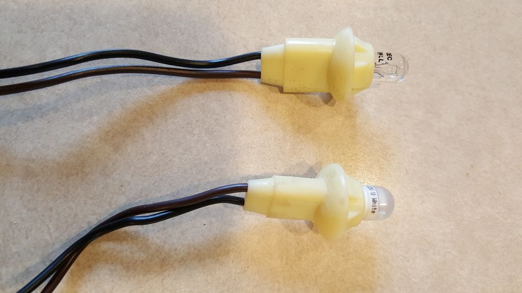
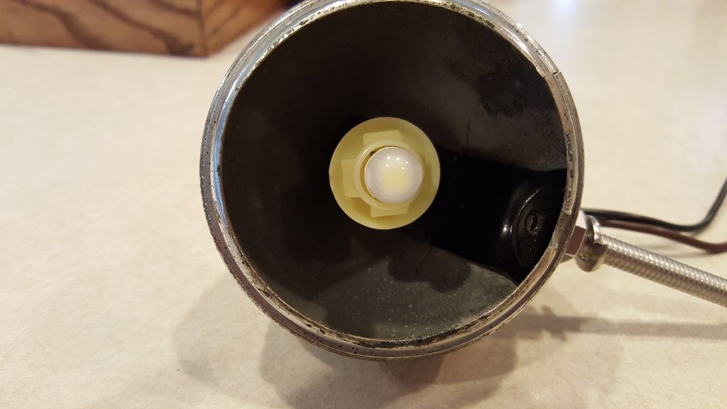
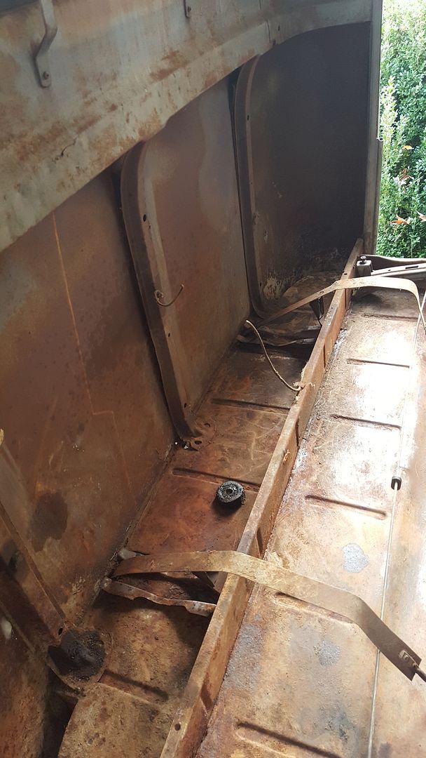
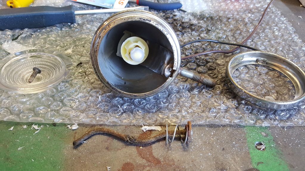
Anyway, after that decision, all that was left was to trim down the bulb holder so that it fit and run the wires.  The trimming was just like the last one, so no problems there.  However, because the bulb holder was still attached to the light housing, I had to fish the wires through the bottom of the bulb holder and over to the light housing exit.  At first, I wanted to keep the original grommet in place, but the hole is small and using another piece of wire for fishing meant that I was going to try to get 3 pieces of wire through a grommet meant for 1 wire.  Wasn't going to work.  So out came the grommet and fortunately, it came out in one piece and was kind of pliable.  After that, fishing the light socket wires was straightforward.  Especially when I used my hooked pick to snag the wires from behind the light bulb holder and bring them to the exit.  After the wires were out, I reinstalled the grommet. Here is a shot of the major components after cleaning and with the new socket, wires and LED bulb installed.  You can see the old wire harness in the foreground and it is clear why I needed to replace it.


Then it was off to make another gasket.  I used the lens cover and the lens as templates for the new gasket.  The next pic shows the stages of cutting the gasket and the tools to do so.


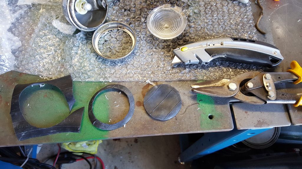
Basically the stages are:

1.  Cut out a chunk of bicycle inner tube big enough to make the gasket and then cut it down the middle to make a square.
2.  Using the glass lens as a template, mark the outer dimension of the gasket and cut out the circle. I used the trimmers to cut out the circle.
3.  Then put the circle into the lens cover and put the glass lens into the cover, but put it in backwards.  That way you can mark the rubber circle for the inside ring, using the lens cover.  I first used the box cutter to trace the outline of the inner circle.  Once I had gone around the circle a couple of times, the box cutter broke through in one place.  Then I used the trimmers to cut out the remaining parts of the circle.
4.  Put the gasket back into the lens cover and mark the opening for the drain hole.  I used small scissors to cut this out.

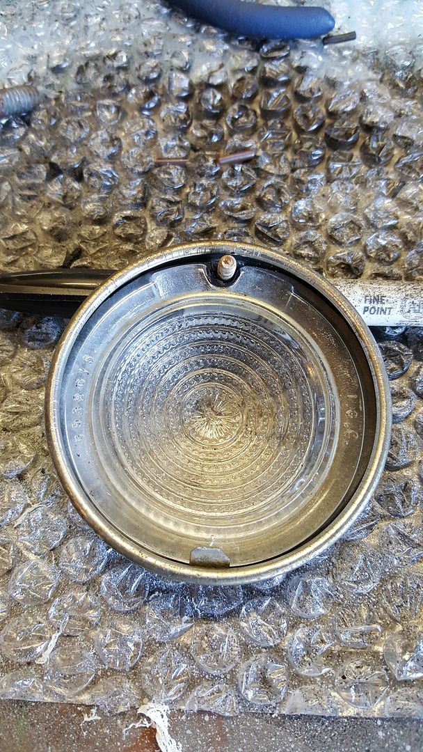
The test fit after all the cutting looked like this:


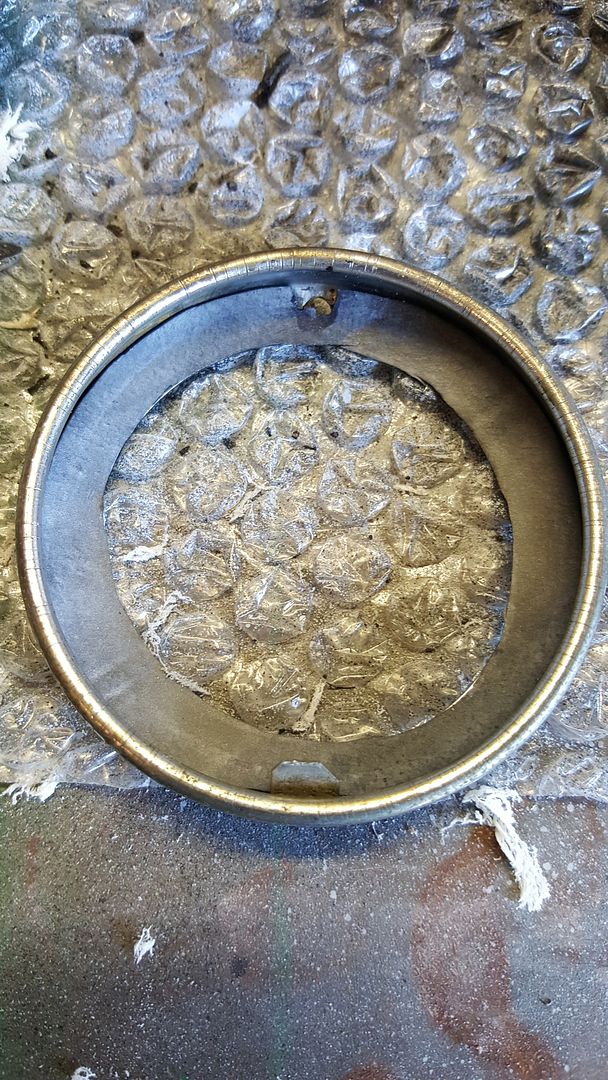
Here it is with the glass lens installed and the attaching screw through the hole.


After all of that, it was time to put the lens and cover back onto the light.  When reassembled, it looked like this:


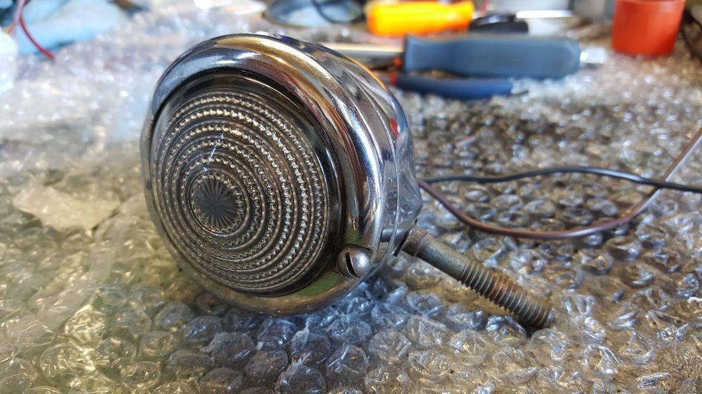
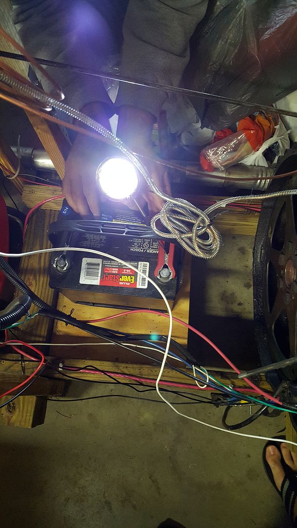
You can see that there is some minor corrosion on the original carriage bolt.  I'll deal with that later. I did do a test of the light to make sure it works, which it did, but I did not take a pic.  Kinda looks like the first one, although you can see the difference in the glass lens.  This one has the "beehive" lens and the BLC light has the "bomber" lens.  Both look good and unless you are right up on them, you could never tell the difference.  Personally, I like the difference.

Stay tuned for the next update.  I hope to work on the 3rd brake light next.  It is not an ordinary light and I'm excited to do the minor fixup necessary to make it work and hold up to the weather.

OBTW, Happy Thanksgiving, Everyone!

Sunday, November 22, 2015

Backup! Lights....

Back up lights were not available for 1953 trucks at all.  Neither as standard equipment nor as a factory option.  Some people added them as aftermarket items, but most people didn't bother.  I wanted them for my truck and I have a few spare circuits on my new wiring harness, so I thought I'd look around to see what was out there.  After searching around online, I decided to go with the Guide Lamp Company (GM's light supplier) B-31 lamps.  They are a teardrop shape with chrome plating on the outside and a clear glass lens.  I found an ebay auction that had 1 B-31 and 1 BLC B-M4 lamp. The BLC lamp is very similar to the B-31, just a little smaller and with a different pattern in the clear glass lens.  Being from the 1940's - 1950's, I figured I'd have to do some clean up and re-wiring to make them suitable for use.  I also wanted to upgrade to LED bulbs.  I wanted the LED bulbs because they tend to be brighter and they have virtually no current draw.

When I got the lamps, I noticed that the BLC lamp had a split in the chrome body that I had not noticed in the auction.  I decided to start the restoration on this one, since it was already damaged and would make a good learning piece.  Here's how it went....

When I got the lamp in the mail and inspected it, I noticed the split.  When I took the lens and cover off, the split looked like this:


It is a pretty big split, running from the lip about an inch and a half.  The metal was too thin for me to try and weld up the split, so I decided to try to save the housing using some JB Weld.  I put the JB Weld in the inside of the housing, forcing some down into the split.  It looked like this when dry:


Nothing fancy here, just really strong epoxy.  I'm hopeful that it, combined with the lens cover, will hold the split from advancing any further.

Next, I turned my attention to the bulb holder assembly.  The original 6v bulb had corroded in the holder, plus there was some surface corrosion on all parts of the holder.  To clean this up, I used the Dremel tool with a mildly abrasive wheel.  It took it right off and had the added benefit of fitting down inside where the bulb sits.  The bulb was a single contact bayonet style bulb and was the same size as the modern 1156 size bulb.  The single contact bayonet style bulb gets current through the single contact and grounds through contact with the side of the bulb holder, which in turn must ground through the chassis or frame.  Since these backup lights were going to be mounted onto the pretty rusty bumper brackets, it was going to be difficult to get a good ground there.  So, I decided that I wanted to switch to a bulb socket that would use 2 contacts instead of 1.  Unfortunately, with this style of bulb holder, 2 contacts means 2 positive contacts, not a positive and negative.  These would be used for brake lights, where you need a low and high and you would use a double filament bulb.  Not what I needed.

I did some research and found that the more recent side marker light used 2 contacts (both positive and negative).  The drawback was that they were designed to snap into the side marker housing and lock in place with a twist, not sit in the can that was used for my bulbs.  However, they were close in size and I figured that I could trim them down a bit and then they'd fit.  Here's a shot of a trimmed socket and an untrimmed socket for comparison:


It may be a little hard to tell in this shot, but the bottom one is trimmed and the top one is original size.  I used the Dremel tool here, too and just took my time and test fit it repeatedly until I got it just right.  It was a snug fit, but the cup near the bulb sits right in the top of the old bulb can and looks like it was meant to be there.  Here's a shot of the bulb socket and pigtail being test fit in the housing:


In this shot you can see that after I took care of the corrosion on the bulb holder I went ahead and painted it.  Since I no longer needed metal to metal contact for the ground connection, there was no need to leave it bare metal, especially since it had already corroded once.  A coat of Rustoleum Automotive Primer and Valspar Satin Black took care of the job nicely.  In this shot, you can see the screw hole for the lens cover to attach to the housing.  The bulb holder assembly is mounted to the housing through a 1/4" carriage bolt that will also secure the lamp to whatever bracket I end up getting to mount the lights to the truck.

Here is an exploded view of all the parts, numbered, so that I can label them for the reader:


1.  Lens Cover
2.  Lens Cover Mounting Screw
3.  Glass Lens
4.  Home Made Rubber Gasket
5.  Socket Pigtail
6.  Stainless Steel Carriage Bolt, Washer, Nut, Lock Washer and Lock Nut
7.  Light Socket Holder
8.  Original Grommet
9.  Lamp Housing

I made the gasket out of an old bicycle inner tube.  I used the glass lens as a template and cut out for the drainage hole that is at the bottom of the light.  I reused the original grommet.  It was kind of hard, so I heated it up with an old hair dryer to soften up the rubber a bit and managed to work it back into place.  The grommet and pigtail exit looked like this:


After assembly, I took it into the garage and did a quick test by touching the wires to a battery.  It looked like this:


Yay, light!

All in all not bad, as long as the JB Weld holds.  We'll see.  Not a difficult project, but one I wanted to get done.  I've still got the B-31 left to do and will tackle that next weekend sometime. I also bought a light that I'm going to use as a 3rd brake light...but that will be the subject of a separate post.

Saturday, November 21, 2015

To The Basement Of The GM Science Building!

A quick post to let everyone know that I've added a link to the GM Heritage Center for the 1953 Chevrolet Truck.  The link is on the Technical Information page, at the top.  The link opens the official Chevrolet Vehicle Information Kit for the 1953 truck and includes tons of useful information. If you work backwards, you can also find links to most of their other vehicles and years.  Enjoy!

Saturday, November 7, 2015

Rusty Mouse Pee and a Stinky Cab

Yesterday was a very long, but very productive day in the garage.  Eight hours worth, to be exact. During that time, I got the truck down off of the jack stands and out into the driveway.  That was the first time that the truck had been outside of the garage in 5 years!  The point of getting it out of the garage was to completely scrub the interior to get rid of the mouse droppings/pee and the attendant smell.  Once I got it off of the stands, I had my helper get into the cab to work the newly refurbished brakes, while I pushed it out.  Before putting our full faith in my brake rebuild, I had my helper test them out by pressing on the brake pedal while I tried to push.  The first attempt was a false start, as I had forgotten to take it out of 1st gear.  After figuring that out, we tried again.  Brake pedal pushed, truck pushed and no movement!  They were holding!  Next it was release the brake pedal, start rolling backwards and engage the pedal again.  The truck instantly stopped!  Repeat several more times until the entire cab was outside.  Chocked all 4 wheels, put the truck back into first gear and she wasn't going to roll anywhere.

Before I could scrub anything, I had to make sure the cab was stripped of everything.  That was the purpose of removing the gauge clusters last weekend.  This time I started with the seat cushions and just put them into the garage for later that day.  Once the cushions were out, I took out the seat frame and put it in the yard for a good scrub with a water/soap/bleach solution and a good scrub brush. After the scrub, it got a good rinse with plain water and put into the sun to dry. Next it was time to take the primary offender out...the gas tank.  The tank was the primary offender because there was a mouse dropping/pee sludge on top of the tank, down the side of the tank and under the tank.  The only way to get it all out was to remove the tank.  I made an effort to remove the clutch head screws that held the sending unit wires to the sending unit, but somehow lost the size 1 clutch head bit. So...time for the wire cutters.  It really didn't make any difference, since I do not plan to reuse the wires.  After that I had to loosen the hold down straps and then the tank came right out.  Here are a series of pics showing the cab before cleaning:


To get a sense of just how dirty the cab floor, especially under where the tank used to be, is to click on the pic and enlarge it.  You'll see a flaky crud that is the mix of rust, droppings and pee that has dried up over the years.  It would always smell like pee whenever it was humid outside. I used the same combo of water, soap and bleach to scrub out the entire cab.  I started with the roof of the cab and worked my way down the sides doing all surfaces including the dash and doors.  I would do a little and then rinse.  After I was done, I took the leaf blower to the water puddles that were inside the cab.  Blew them right out!  I propped open the doors and let the nice breeze blow through the truck to dry it out.  While I was waiting for the inside to dry, I went back in the garage and stripped the old upholstery off of the seat back and bottom cushions.  It was gnarly!  I did find a nice, neat 1" diameter hole in the material where a little field mouse had gnawed  a hole through and got his nest material....  Once the frames were stripped, they got the same treatment.  Scrubbed and rinsed and set out in the yard to dry.

After drying the inside of the cab looked like this:


You can see that the pile of crud is gone.  You can also see the remnants of body sealer that the factory used to seal the seat apron joint to the cab floor.  Everything had a nice bleach smell.  A dramatic improvement!

Once the frames were dry, I simply oiled the seat adjustment rails, reattached the seat frame and bolted it down.  Then I set the seat cushion frames back into place and called for my helper.  With the help of a 3rd helper, we pushed the truck back into the garage and chocked the wheels.  She is now ready for a long winter of rewiring, gauge cluster refurbishment and the beginnings of removing bits from the installed engine in preparation for the engine swap next spring.

As a side note, in order to get the gas tank out, I first had to remove the petcock that was attached to the bottom of the tank.  I actually did that before getting the truck down off of the jack stands.  It was funny because when I got the petcock off of the pipe nipple I could see that the pipe nipple was completely blocked with dried mud.  It was interesting, but I didn't really think about it until I was moving the tank into the back yard.  When I was moving it, I could hear dried mud sliding around in the tank.  I didn't check to see exactly how much dirt and debris was actually in the tank, but it seems likely that I'll end up replacing the tank instead of reusing it, unless I can find someone to boil it out and it turns out to be free of holes.

All in all, it was a lot of work and a very long day, boiled down into a couple of paragraphs.  By the end of the day, I was exhausted and very sore, but it was likely the last 80 degree day and I knew I had to get it done, so I did.

Oh yeah, and I only got stung by 1 bee while I was working.  I don't know what the yellow jackets like about the smell of the Kroil, but it makes them come buzzing around and 1 of them decided that I needed to be stung.  Go figure.

Sunday, November 1, 2015

The Bleeding Has Stopped!

Yesterday was a very productive day in the garage.  It was a long day, but a productive day.  I started out determined to use the new brake adjustment tool (officially called a brake spoon) to adjust the brake shoes.  Once that was done, I could move back to bleeding the brakes.  As you may recall, I got as far in the process of loosening all 4 anchor pin nuts and actually adjusting the brake shoes on 1 wheel.  Then I found out that I needed the brake spoon to make the final adjustment.  During the week, I went to the FLAPS and got the tool.  Yesterday, I got under the truck and found that the tool worked wonderfully well!  Armed with this new tool, I set out to do the remaining 3 wheels.  It actually went very quickly and I was very happy with the results. Then it was back to bleeding the brakes.

For this effort, I had no helper.  It was just me, an empty soda bottle with a hole drilled in the cap and a clear, flexible hose.  This turned out to be pretty simple, too.  I was very cautious to make sure that I didn't drain the master cylinder and reintroduce air into the brake lines, constantly going from the master cylinder, to the wheel being bled and back again.  Each time pumping the brake pedal and then checking to see if fluid or bubbles could be seen.  Once I was satisfied that the line was clear, I tightened the bleed valve and was off to the next wheel.  The sequence, according to the shop manual, is:  left rear, right rear, right front and left front.  This takes you from the farthest point from the master cylinder to the closest. Once all 4 wheels had been bled, it was time to fill the master cylinder, put the cap back on and pump the pedal!  VOILA!  It works!  I got steady pedal pressure.

After getting steady pressure, I went back under the truck to check for leaks and found 2 small ones. One leak was at the rear junction block where the hard line is split between left and right wheels.  The other was at the master cylinder where the separate hard line joins the junction block to go to the left front wheel.  Using the correct line wrench (a flare nut wrench), I flanged down on both offenders and problem solved.

Feeling pretty good about things, I decided to start in on stripping the interior of things that I didn't want ruined when I scrub out the interior.  I need to scrub out the interior, because mice had lived in the truck when it was out in the field and the inside smells of mouse pee!  So, knowing that I will want to save the gauges, I decided to start there.

It was very difficult to reach the nuts that hold the speedometer and gauge cluster to the dash, as they are true blind connections.  After fiddling with wrenches, sockets, etc, I was finally able to remove both parts to the gauge cluster.  The looked like this when out of the truck:


Here's a closeup of the speedometer/odometer:


Here's a closeup of the gauge cluster:


Here's a shot of the backs of the gauges:


And here is the money shot, an extreme closeup of the odometer where you can actually make out the original miles on the truck (61590.?):


Even enlarging the pic or looking under really bright lights, I could not figure out the tenths of a mile number.  I guess I'll have to wait until I drive it and it rolls to the next digit, which won't be faded. Then I'll know.

So now that the gauges are out, I have to remove the seat and frame so that I can get to the gas tank. The tank needs to come out, as that is where a lot of the crud still remains inside the truck. Once those are out, I plan to scrub the interior with bleach/water and then rinse it out. Afterwards, I can refurbish the gas tank and reinstall, then refurbish the seat and frame and then the gauges. Then I can set about removing the old wire harness and installing the new wire harness.  Then, it is time to think about getting the old tranny out and transferred to the replacement engine....  But, one step at a time.

Friday, October 30, 2015

Brake Bleeding Update

Well...I started the process of bleeding the brakes and found out that it wasn't as straightforward as I had hoped that it would be.  In fact, being a noob at all of this, I made some mistakes.  So, here's the story so far:

I started by filling the reservoir.  Then, according to the Chevy shop manual for my truck, I should start the bleeding process on the rear driver's side wheel.  So I went under the truck and loosened the brake bleeder valve and hooked a piece of clear hose to the nipple on the valve and put the other end into an old plastic bottle.  Then I went to the brake pedal and worked it back and forth with my hand, pumping the brake fluid into the system.  After a couple of pumps, I would refill the reservoir and pump some more.  After a while, I checked the bottle to see if any fluid had reached that wheel, being the farthest from the master cylinder.  If no fluid, then I repeated the process until fluid did appear. Once fluid appeared, I got my helper to sit in the truck and work the pedal for me, while I was under the truck waiting for the bubbles to stop and then I could tighten the valve and move to the next wheel.  Unfortunately, I forgot to tell my helper to watch the fluid level in the master cylinder and we pumped it dry, forcing air back into the brake lines and ruining our earlier effort.   Time for a break.

After thinking about it for a while, I decided to get a "one man" brake bleeder tool.  Basically, you attach it to the brake bleeder valve, open it slightly and then squeeze the handle on the tool and it draws a vacuum and sucks the air and fluid out of the line.  Similarly, once the bubbles are gone, you tighten the valve and move on.  However, I never could seem to get a tight fit with the adapter that hooks onto the valve.  So I decided to go onto my truck forum and ask about the whole brake bleeding process.  Once I had posted my question, I got some disappointing feedback.  Unbeknownst to me, I had omitted an entire step in the brake rebuild process. According to the forum members and then backed up in the shop manual, I was supposed to adjust the new brake shoes prior to bleeding the system.  That meant a whole new set of steps before I can go back to bleeding. Those steps included loosening the anchor pin nut on the back of the backer plate.  The nut can be seen in this picture.  It is the very large, rusty nut above the new wheel cylinder.


The nut is 15/16" and is supposed to be torqued at 60-80 ft-lbs when done.  Add to that rust and dirt and 60 years and that thing was on tight.  I soaked all 4 of these nuts with AeroKroil and let them sit for a full day.  Then I came back with a breaker bar and a 3 foot long pipe as an extender.  Between the breaker bar and the extender, I had enough leverage to break all 4 nuts free.  After that, you are supposed to adjust the star wheel through the slot in the backer plate.


This pic shows the anchor pin at the top.  It's where the brake shoe return springs attach.  It also shows the brake shoe adjuster with the star wheel.  The backer plate has a slot cut into it, so that you can adjust the brake shoes without having to take the drum off.

Anyway, you are supposed to adjust the brake shoes by rotating the star wheel until "heavy drag" is felt when rotating the wheel.  Once you have heavy drag (and the anchor pin nut is loosened, but not too loose) you are supposed to tap on the backer plate and nut and then check to see if the drag changed any.  If it did, then you rotate the star wheel some more, tap some more and check the drag some more.  Once you go through the process and the drag does not change between pre taps and post taps, you know the brake shoes are centered within the brake drum. Then you tighten the anchor pin nut to the proper torque.  Then you rotate the star wheel in the opposite direction by the specified number of clicks.  This moves the brake shoes away from the brake drum and removes the heavy drag.  Then you can put the cover back into the slot and move onto the next wheel.  Once all of the wheels are done, then you can bleed the brakes.

I got as far as the last adjustment on the star wheel on the first wheel.  I had been rotating the star wheel with a screwdriver.  It worked ok on tightening the star wheel but was completely inadequate for loosening it.  So, I had to stop the adjustment and go to the FLAPS for the special tool (ie, a heavy duty bent screwdriver).  And that's where I'm at currently.  Waiting for some time to go out and make that last adjustment and move on to the other wheels.  Then I can start bleeding the brakes again.  In the interim, I've learned that it takes a whole lot more brake fluid to clear out a brand new set of lines than I had originally though.  So I'll also stock up on that. Hopefully this weekend I'll get some of it done.  One thing is for sure, it is a learning process!

Saturday, October 17, 2015

Brake System Replacement Complete, But There Will Still Be Bleeding

A major milestone was achieved today...the complete brake system replacement was finished! Everything from the master cylinder out to each wheel cylinder, including all of the hard and soft lines, the brake shoes, springs retainers and spreaders.  Everything.  Here's a panoramic look at the master cylinder and lines over to the passenger side frame junction block:


As a point of reference, here's a drawing from the factory assembly manual showing where this equipment is located on the truck:


Here's the panoramic pic from a couple of months ago, showing where we started:


In this pic, I had already cut off the  brake line fittings and removed the master cylinder junction block and the infamous banjo bolt.  The contrast between the before and after is pretty stark. Even more so when you consider that I really didn't set out to clean anything, just remove the crud so that I could remove the old brake lines.  Which is what I did.

Here are some close up pics, starting with the new master cylinder:


This gives you a really nice view of the new master cylinder with the new hard lines and the old junction block and banjo bolt reinstalled.  This also gives you a good view of the routing of the brake line that goes to the front left wheel cylinder that I mentioned in an earlier post.  You can see it has to snake past where the brake pedal and clutch pedal connect and then past the transmission shift linkages.  It is a tight fit, but it does fit.

Next is a pic of the hard line that runs from the master cylinder, across the frame crossmember and to the passenger side frame rail, where it connects to the junction block with the blind connection.  The hard line looks like this:


This is one of those situations that I was talking about in an earlier post.  The brake lines were purchased premanufactured for my truck.  However, that doesn't mean they just dropped into place! This line was supposed to ride along the bottom of the crossmember....  You can see that I had to rotate the clip that holds the line to the cross member.  In the end, it did connect up to the junction block, which is what was important, not riding in the cross member.  Here's another shot of the far end of this hard line:


The giant greasy blob on the left is the transmission.  I hope to remove it this winter in preparation for transplanting the engine next spring.  Just as a point of interest, this pic shows that to remove the transmission from the bell housing, you have 2 bolts that bolt the transmission to the bellhousing from the outside and 2 from inside the bellhousing!  That means you have to reach into the bellhousing from underneath to get to the bolts.  That means removing the inspection shield at a minimum.  I'm not sure what else is involved....

The blind connection junction block looks like this now:


Once again, I just jammed the phone up into the space where I don't fit and snapped this pic. Looks like I need to run the shop vac up there and get out the rust and dirt!  What you are looking at in this pic is the larger diameter line going into the junction block is from the master cylinder. The line on the left goes to the right front wheel cylinder and the line on the right goes to the rear end, where it is split between left and right wheel cylinders.  The connection at the rear junction block first passes through a soft line and looks like this:


So that's it!  Next, it's time to fill the master cylinder and start bleeding the system.  With any luck, I won't have any leaks!  If I do, then I'll have to go back under and try to tighten the offending connection.  Hopefully I'll have a short post with those results in a couple of days.

Thursday, October 8, 2015

I'm Throwing These Clothes Away!

With a title like that, you know it was a good day in the garage!  I intentionally wore the rattiest clothes that I had, because I knew it was going to be a dirty day.  Today, I got down to business on the left front brake replacement.  As I knew, I had to drill out the rivets that were holding the brake drum to the wheel assembly.  Just to prove that I'm not over exaggerating, here's a shot of the drum (with rivets) before I got to work:


You can clearly see the evenly spaced 6 wheel lugs and in between the lugs you can see the 3 rivets. Here is a closeup after grinding the heads off and drilling out the rivets:


Another thing that is interesting in that pic is that you can see a ring around the drilled out hole.  That ring is the actual rivet in the brake drum hole.  What makes it interesting is that ring shows because the Aerokroil (penetrating oil) that I had been spraying into the lugs and the other holes in the drum had crept around the back side of the drum and found its way to the rivets and had enough room to creep between the rivet and the drum.  That stuff is about the best penetrating oil around.

Once I got to that stage, I knew it was only a matter of time before the drum was off.  Once it was off, it looked like this:


Which is about the same as the right front.  Here's a shot from a different angle:


Here it is after being cleaned:


What I've learned through this rebuild, is that there is a specific process that you need to follow.  So once everything was off and clean, it was time to rebuild.  The steps are:

1.  Remove bleed valve from wheel cylinder
2.  Insert wheel cylinder into backing plate and attach with screws and lock washers
3.  Reattach bleed valve
4.  Attach soft brake hose and copper washer to wheel cylinder
5.  Attach soft brake hose to brake hard line
6.  Attach brake hose clip to bracket on frame.

In my case, since I wasn't reusing the hard line, I had an extra step between steps 4 and 5.  That step was to remove the old hard line and route/attach the new hard line from the master cylinder to the point in the frame where the bracket is.  As usual, this was much harder than it should have been. The routing from the master cylinder was very tight and required several attempts before I figured out exactly where it had to go.  The route takes it past the master cylinder, around the brake pedal attach point and past the gear shift linkages on the side of the transmission.  In reality, there is only one way it can go.  It just took me a while to figure out what that way was.  Once all of the steps were done, it looked like this:


When I was assembling this wheel, I realized that I forgot to add the anti-sieze around the wheel hub on the right wheel that I did yesterday.  Probably not a big deal, as I doubt that this brake drum will sit on that hub for 60 years without being removed like the last one did!  Nevertheless, I did add it to this wheel hub.

So that's it for the wheel rebuilds.  Next up is for me to tighten each connection to the proper tightness.  Then I can fill the system with brake fluid and bleed the system.  In theory, at that point, I should be able to use the brakes to stop the truck!

One thing that I realized after spending so much time under the truck, is that I can not get away without an emergency brake rebuild.  So, sadly, that will mean tearing up the rear brakes again, when I get the parts for the e-brake.  That will be on another day, though.

That's all for now.  I'll update this when I've got fluid in the system....

Wednesday, October 7, 2015

Progress! The 1/2 Ton Truck has 3/4th Of It's Brakes!

Today was a mental health day!  Tomorrow will be one, too!  Now that the hot weather is behind us, it is actually enjoyable to be out in the garage working.  I've got this unfinished project that has been taunting me all summer long.  So it's time to get it finished.  When I last worked on the truck brakes, you may recall that I had a difficult time getting the front hub off.  That was because Chevy decided to rivet them to the axle assembly.  After a bunch of grinding, I managed to get the right front hub off, but by then, I was completely worn out and had to quit for the day.  I had no idea that I wouldn't touch it again for 5 months!  But today was the day.  When I got the wheel and hub off, the old assembly looked like this:


Kinda gnarly.  Brake dust, rust, spider webs , dead bugs and old grass.  Just like the rest of the truck! So I set off to do the disassembly, which was pretty uneventful.  After removing the old parts and cleaning the backer plate with some brake cleaner, I added the new wheel cylinder.  It looked like this:


Nothing about this experience has been easy, so this wasn't expected to be either.  And it wasn't. The picture of the new wheel cylinder installed hides the issues that I went through to get it there. Those included 2 trips to the home store for hardware, searching in vain just about everywhere in my garage for the missing hardware and then finding out that the wheel cylinder in the box labelled right front didn't fit.  That last one is a mystery.  I could have accidentally switched them last winter when I got them, they could have been put in the wrong boxes before I got them or maybe the wheel hub assemblies were put on the wrong sides.  Who knows, but probably the first option. My first clue was when the wheel cylinder labelled for front right would not go into the opening on the wheel backer plate.  No matter how I tried to wiggle it in, it would not go.  So I compared it to the original and found that the brake hose opening was on the wrong side of the wheel cylinder (front instead of back).  I then got the other wheel cylinder out of the box and compared it to the original and it matched.  So I tried to get it into position on the backer plate and it just dropped right into place.  Go figure.  When I hooked up the brake hose to the wheel cylinder and the hard brake line, it was bent exactly like the original hose.  I gave the wheel a tug to see if the hose would kink when the steering was turned, but it didn't kink, so that's how I left it.  The soft hose connection to the hard line looks like this:


The soft hose connection to the wheel cylinder looks like this:


In these pics,, you can see that I also replaced the attaching hardware.  In the top pic, you can see the retaining clip on the back side.  In the bottom pic, you can see the copper washer that came with the wheel cylinder and new, grade 8 bolts and lock washers to hold the wheel cylinder to the backer plate.

Under the truck, I also replaced the old master cylinder with the new one.  For a refresher, here's what the old one looked like before I starting cutting out the old brake lines:


Here's the new one compared to the old one:


And with the infamous banjo bolt and J Block attached:


From a step 1, step 2 perspective, I actually replaced the master cylinder first, then installed the hard line that connects the master cylinder to the far side of the frame J block that distributes brake fluid to the right front and both back wheel cylinders.  Getting that J block connected to the 3 different brake lines that attach to it was one of the hardest things that I've done so far.  It is almost a blind connection and it is in a very confined space.  Here's what it looked like when I was done:


You look at the pic and think, that's not a blind connection!  In reality, I just shoved the phone up there where I could not get my head and took the pic.  What you see in the pic is the cross member that holds the transmission on the left, 3 brake hard lines attaching to the J block, which is screwed into the frame rail.  Also, you can see the bottom of the frame rail.  What you can't see is just off screen on the right...another cross member.  The fat line in the foreground is the fuel line, which is still to be replaced.  On top of the blind connection issue, is the issue that the brake hard lines are made for this truck, but that does not mean that they bolt right up!  Nope, you gotta finesse them. Alot.  That meant going back to the rear of the truck, disconnecting the rear of the hard line on the right in the above pic, making the connection that you see above.  Then going back to the rear of the truck and reconnecting the hard line there.  That connection looks like this:


It was much easier to make the blind connection first, then wiggle the hard line around until it matched up with the hose connection again.  So that's what I did.  Then it was back to the front wheel reassembly.  I attached the hard line and soft hose as shown above, then replaced the brake shoes, springs, clips, adjusters, et al.  It looks like this now:


Then all I had to do was add the new brake drum and we were done.  It now looks like this:


Once the wheel was back on, I gave it a spin and it sounded great!  No grinding in the bearings and no sound of the new drum hitting the shoes.  I'll adjust the shoes later, after I get done with the install and add brake fluid to the system.

That's all for now.  Tomorrow, I'm planning to attack the left front and add the last hard line.  If I can get that done, I'll be ready for brake fluid!