1953 chevy truck ad

1953 chevy truck ad

Friday, October 30, 2015

Brake Bleeding Update

Well...I started the process of bleeding the brakes and found out that it wasn't as straightforward as I had hoped that it would be.  In fact, being a noob at all of this, I made some mistakes.  So, here's the story so far:

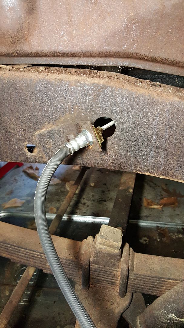
I started by filling the reservoir.  Then, according to the Chevy shop manual for my truck, I should start the bleeding process on the rear driver's side wheel.  So I went under the truck and loosened the brake bleeder valve and hooked a piece of clear hose to the nipple on the valve and put the other end into an old plastic bottle.  Then I went to the brake pedal and worked it back and forth with my hand, pumping the brake fluid into the system.  After a couple of pumps, I would refill the reservoir and pump some more.  After a while, I checked the bottle to see if any fluid had reached that wheel, being the farthest from the master cylinder.  If no fluid, then I repeated the process until fluid did appear. Once fluid appeared, I got my helper to sit in the truck and work the pedal for me, while I was under the truck waiting for the bubbles to stop and then I could tighten the valve and move to the next wheel.  Unfortunately, I forgot to tell my helper to watch the fluid level in the master cylinder and we pumped it dry, forcing air back into the brake lines and ruining our earlier effort.   Time for a break.

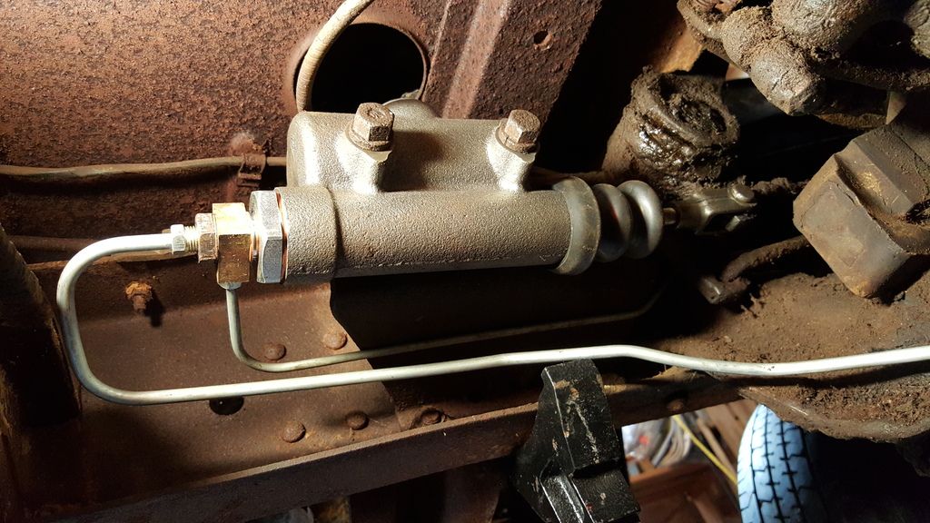
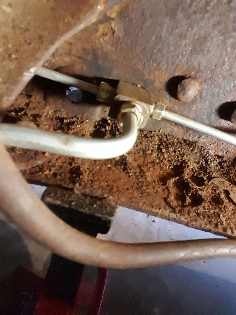
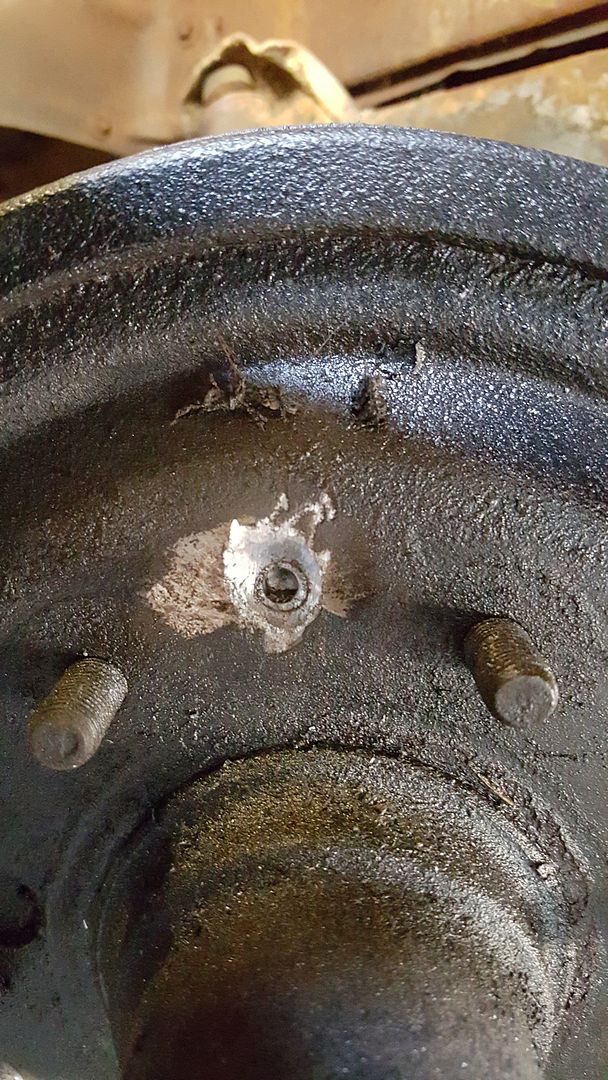
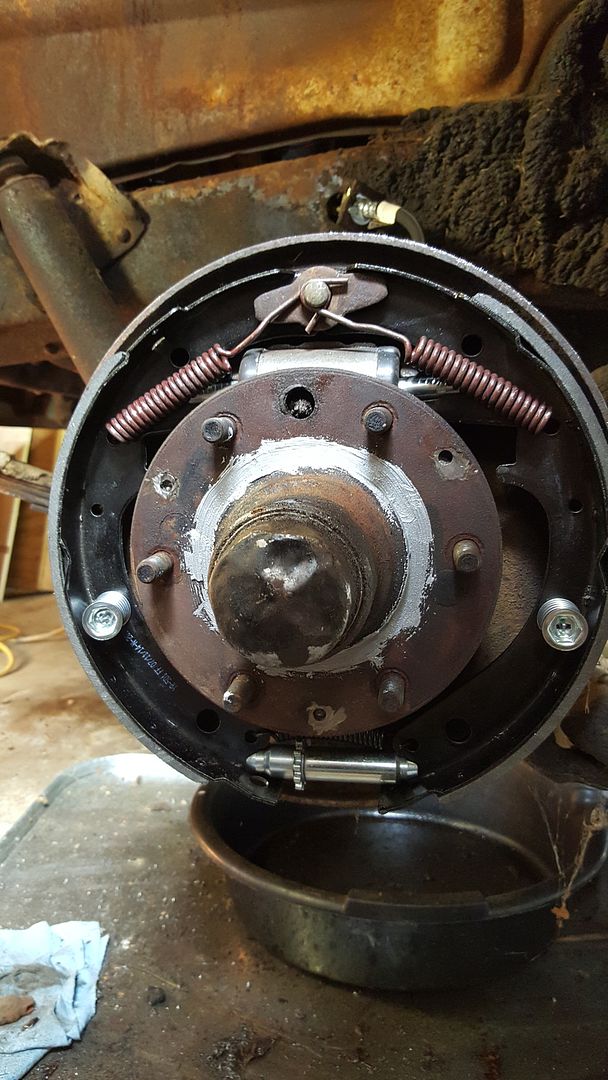
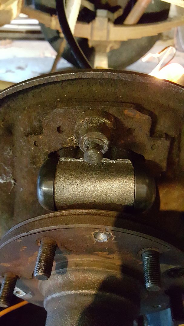
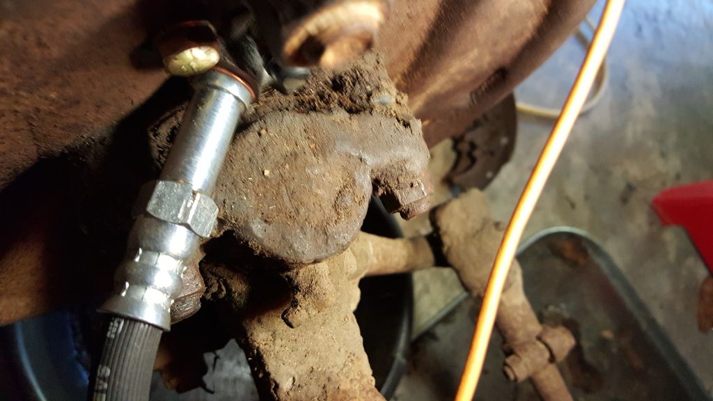
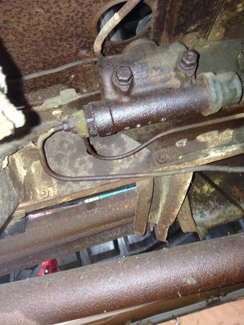
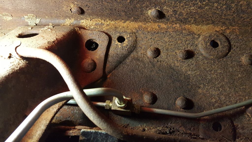
After thinking about it for a while, I decided to get a "one man" brake bleeder tool.  Basically, you attach it to the brake bleeder valve, open it slightly and then squeeze the handle on the tool and it draws a vacuum and sucks the air and fluid out of the line.  Similarly, once the bubbles are gone, you tighten the valve and move on.  However, I never could seem to get a tight fit with the adapter that hooks onto the valve.  So I decided to go onto my truck forum and ask about the whole brake bleeding process.  Once I had posted my question, I got some disappointing feedback.  Unbeknownst to me, I had omitted an entire step in the brake rebuild process. According to the forum members and then backed up in the shop manual, I was supposed to adjust the new brake shoes prior to bleeding the system.  That meant a whole new set of steps before I can go back to bleeding. Those steps included loosening the anchor pin nut on the back of the backer plate.  The nut can be seen in this picture.  It is the very large, rusty nut above the new wheel cylinder.


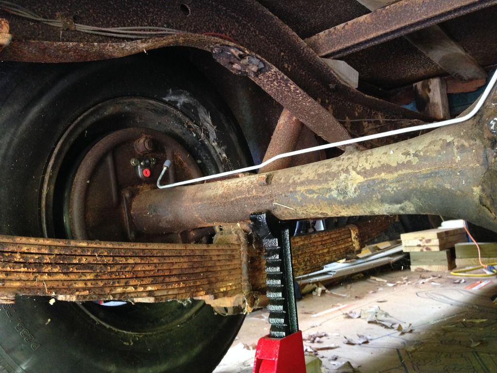
The nut is 15/16" and is supposed to be torqued at 60-80 ft-lbs when done.  Add to that rust and dirt and 60 years and that thing was on tight.  I soaked all 4 of these nuts with AeroKroil and let them sit for a full day.  Then I came back with a breaker bar and a 3 foot long pipe as an extender.  Between the breaker bar and the extender, I had enough leverage to break all 4 nuts free.  After that, you are supposed to adjust the star wheel through the slot in the backer plate.


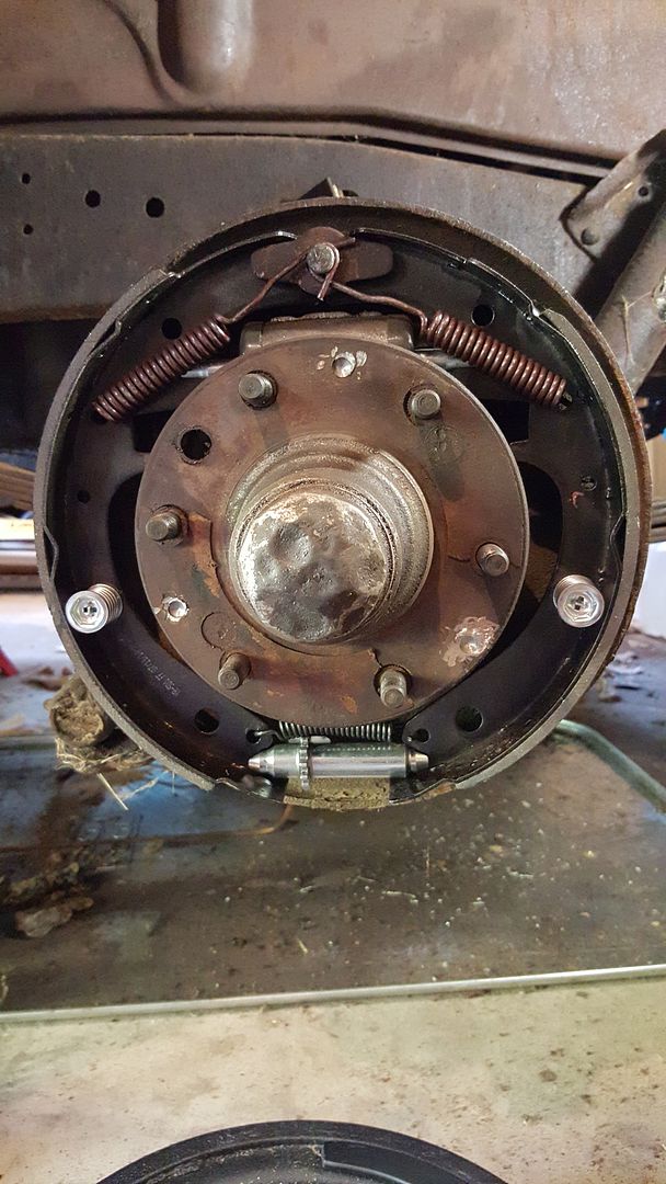
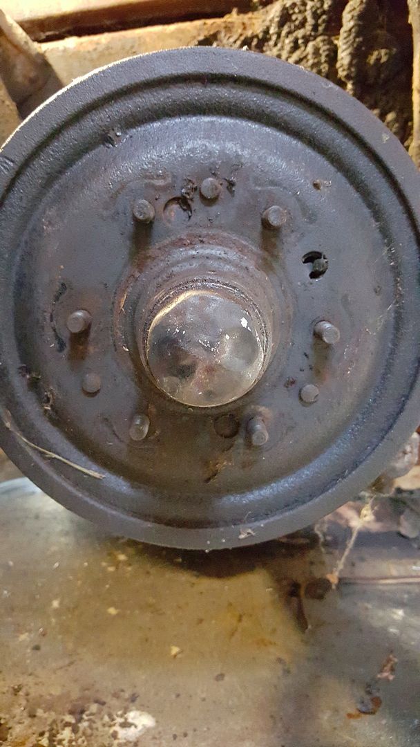
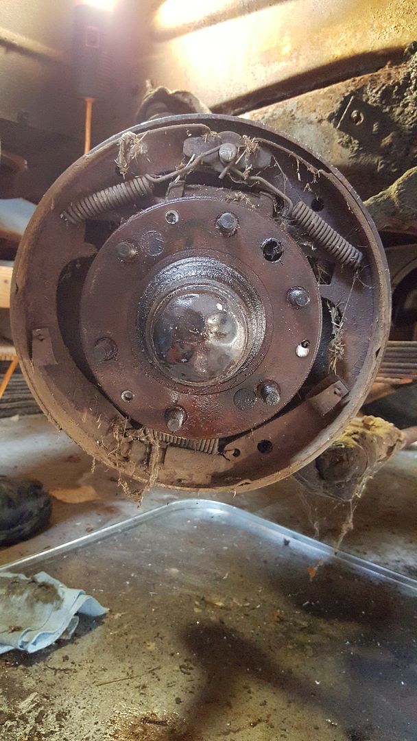
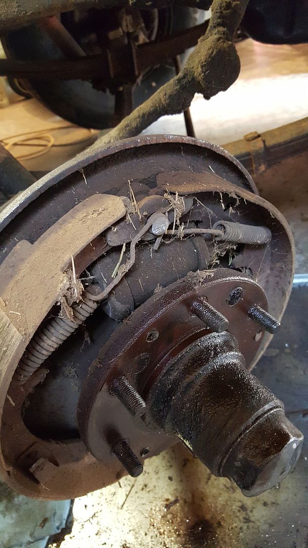
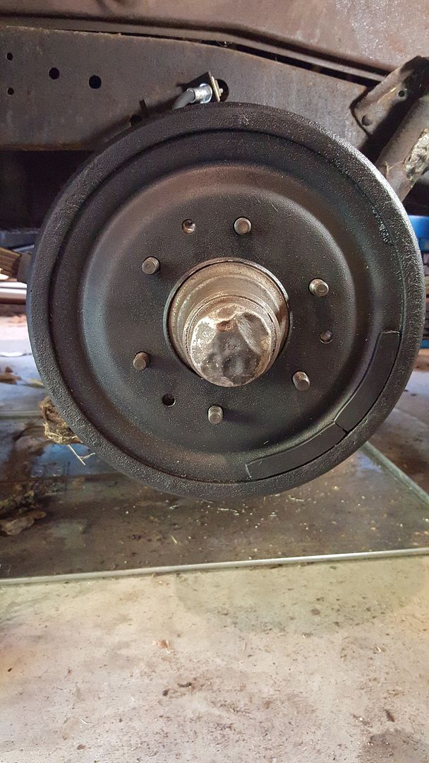
This pic shows the anchor pin at the top.  It's where the brake shoe return springs attach.  It also shows the brake shoe adjuster with the star wheel.  The backer plate has a slot cut into it, so that you can adjust the brake shoes without having to take the drum off.

Anyway, you are supposed to adjust the brake shoes by rotating the star wheel until "heavy drag" is felt when rotating the wheel.  Once you have heavy drag (and the anchor pin nut is loosened, but not too loose) you are supposed to tap on the backer plate and nut and then check to see if the drag changed any.  If it did, then you rotate the star wheel some more, tap some more and check the drag some more.  Once you go through the process and the drag does not change between pre taps and post taps, you know the brake shoes are centered within the brake drum. Then you tighten the anchor pin nut to the proper torque.  Then you rotate the star wheel in the opposite direction by the specified number of clicks.  This moves the brake shoes away from the brake drum and removes the heavy drag.  Then you can put the cover back into the slot and move onto the next wheel.  Once all of the wheels are done, then you can bleed the brakes.

I got as far as the last adjustment on the star wheel on the first wheel.  I had been rotating the star wheel with a screwdriver.  It worked ok on tightening the star wheel but was completely inadequate for loosening it.  So, I had to stop the adjustment and go to the FLAPS for the special tool (ie, a heavy duty bent screwdriver).  And that's where I'm at currently.  Waiting for some time to go out and make that last adjustment and move on to the other wheels.  Then I can start bleeding the brakes again.  In the interim, I've learned that it takes a whole lot more brake fluid to clear out a brand new set of lines than I had originally though.  So I'll also stock up on that. Hopefully this weekend I'll get some of it done.  One thing is for sure, it is a learning process!

Saturday, October 17, 2015

Brake System Replacement Complete, But There Will Still Be Bleeding

A major milestone was achieved today...the complete brake system replacement was finished! Everything from the master cylinder out to each wheel cylinder, including all of the hard and soft lines, the brake shoes, springs retainers and spreaders.  Everything.  Here's a panoramic look at the master cylinder and lines over to the passenger side frame junction block:


As a point of reference, here's a drawing from the factory assembly manual showing where this equipment is located on the truck:


Here's the panoramic pic from a couple of months ago, showing where we started:


In this pic, I had already cut off the  brake line fittings and removed the master cylinder junction block and the infamous banjo bolt.  The contrast between the before and after is pretty stark. Even more so when you consider that I really didn't set out to clean anything, just remove the crud so that I could remove the old brake lines.  Which is what I did.

Here are some close up pics, starting with the new master cylinder:


This gives you a really nice view of the new master cylinder with the new hard lines and the old junction block and banjo bolt reinstalled.  This also gives you a good view of the routing of the brake line that goes to the front left wheel cylinder that I mentioned in an earlier post.  You can see it has to snake past where the brake pedal and clutch pedal connect and then past the transmission shift linkages.  It is a tight fit, but it does fit.

Next is a pic of the hard line that runs from the master cylinder, across the frame crossmember and to the passenger side frame rail, where it connects to the junction block with the blind connection.  The hard line looks like this:


This is one of those situations that I was talking about in an earlier post.  The brake lines were purchased premanufactured for my truck.  However, that doesn't mean they just dropped into place! This line was supposed to ride along the bottom of the crossmember....  You can see that I had to rotate the clip that holds the line to the cross member.  In the end, it did connect up to the junction block, which is what was important, not riding in the cross member.  Here's another shot of the far end of this hard line:


The giant greasy blob on the left is the transmission.  I hope to remove it this winter in preparation for transplanting the engine next spring.  Just as a point of interest, this pic shows that to remove the transmission from the bell housing, you have 2 bolts that bolt the transmission to the bellhousing from the outside and 2 from inside the bellhousing!  That means you have to reach into the bellhousing from underneath to get to the bolts.  That means removing the inspection shield at a minimum.  I'm not sure what else is involved....

The blind connection junction block looks like this now:


Once again, I just jammed the phone up into the space where I don't fit and snapped this pic. Looks like I need to run the shop vac up there and get out the rust and dirt!  What you are looking at in this pic is the larger diameter line going into the junction block is from the master cylinder. The line on the left goes to the right front wheel cylinder and the line on the right goes to the rear end, where it is split between left and right wheel cylinders.  The connection at the rear junction block first passes through a soft line and looks like this:


So that's it!  Next, it's time to fill the master cylinder and start bleeding the system.  With any luck, I won't have any leaks!  If I do, then I'll have to go back under and try to tighten the offending connection.  Hopefully I'll have a short post with those results in a couple of days.

Thursday, October 8, 2015

I'm Throwing These Clothes Away!

With a title like that, you know it was a good day in the garage!  I intentionally wore the rattiest clothes that I had, because I knew it was going to be a dirty day.  Today, I got down to business on the left front brake replacement.  As I knew, I had to drill out the rivets that were holding the brake drum to the wheel assembly.  Just to prove that I'm not over exaggerating, here's a shot of the drum (with rivets) before I got to work:


You can clearly see the evenly spaced 6 wheel lugs and in between the lugs you can see the 3 rivets. Here is a closeup after grinding the heads off and drilling out the rivets:


Another thing that is interesting in that pic is that you can see a ring around the drilled out hole.  That ring is the actual rivet in the brake drum hole.  What makes it interesting is that ring shows because the Aerokroil (penetrating oil) that I had been spraying into the lugs and the other holes in the drum had crept around the back side of the drum and found its way to the rivets and had enough room to creep between the rivet and the drum.  That stuff is about the best penetrating oil around.

Once I got to that stage, I knew it was only a matter of time before the drum was off.  Once it was off, it looked like this:


Which is about the same as the right front.  Here's a shot from a different angle:


Here it is after being cleaned:


What I've learned through this rebuild, is that there is a specific process that you need to follow.  So once everything was off and clean, it was time to rebuild.  The steps are:

1.  Remove bleed valve from wheel cylinder
2.  Insert wheel cylinder into backing plate and attach with screws and lock washers
3.  Reattach bleed valve
4.  Attach soft brake hose and copper washer to wheel cylinder
5.  Attach soft brake hose to brake hard line
6.  Attach brake hose clip to bracket on frame.

In my case, since I wasn't reusing the hard line, I had an extra step between steps 4 and 5.  That step was to remove the old hard line and route/attach the new hard line from the master cylinder to the point in the frame where the bracket is.  As usual, this was much harder than it should have been. The routing from the master cylinder was very tight and required several attempts before I figured out exactly where it had to go.  The route takes it past the master cylinder, around the brake pedal attach point and past the gear shift linkages on the side of the transmission.  In reality, there is only one way it can go.  It just took me a while to figure out what that way was.  Once all of the steps were done, it looked like this:


When I was assembling this wheel, I realized that I forgot to add the anti-sieze around the wheel hub on the right wheel that I did yesterday.  Probably not a big deal, as I doubt that this brake drum will sit on that hub for 60 years without being removed like the last one did!  Nevertheless, I did add it to this wheel hub.

So that's it for the wheel rebuilds.  Next up is for me to tighten each connection to the proper tightness.  Then I can fill the system with brake fluid and bleed the system.  In theory, at that point, I should be able to use the brakes to stop the truck!

One thing that I realized after spending so much time under the truck, is that I can not get away without an emergency brake rebuild.  So, sadly, that will mean tearing up the rear brakes again, when I get the parts for the e-brake.  That will be on another day, though.

That's all for now.  I'll update this when I've got fluid in the system....

Wednesday, October 7, 2015

Progress! The 1/2 Ton Truck has 3/4th Of It's Brakes!

Today was a mental health day!  Tomorrow will be one, too!  Now that the hot weather is behind us, it is actually enjoyable to be out in the garage working.  I've got this unfinished project that has been taunting me all summer long.  So it's time to get it finished.  When I last worked on the truck brakes, you may recall that I had a difficult time getting the front hub off.  That was because Chevy decided to rivet them to the axle assembly.  After a bunch of grinding, I managed to get the right front hub off, but by then, I was completely worn out and had to quit for the day.  I had no idea that I wouldn't touch it again for 5 months!  But today was the day.  When I got the wheel and hub off, the old assembly looked like this:


Kinda gnarly.  Brake dust, rust, spider webs , dead bugs and old grass.  Just like the rest of the truck! So I set off to do the disassembly, which was pretty uneventful.  After removing the old parts and cleaning the backer plate with some brake cleaner, I added the new wheel cylinder.  It looked like this:


Nothing about this experience has been easy, so this wasn't expected to be either.  And it wasn't. The picture of the new wheel cylinder installed hides the issues that I went through to get it there. Those included 2 trips to the home store for hardware, searching in vain just about everywhere in my garage for the missing hardware and then finding out that the wheel cylinder in the box labelled right front didn't fit.  That last one is a mystery.  I could have accidentally switched them last winter when I got them, they could have been put in the wrong boxes before I got them or maybe the wheel hub assemblies were put on the wrong sides.  Who knows, but probably the first option. My first clue was when the wheel cylinder labelled for front right would not go into the opening on the wheel backer plate.  No matter how I tried to wiggle it in, it would not go.  So I compared it to the original and found that the brake hose opening was on the wrong side of the wheel cylinder (front instead of back).  I then got the other wheel cylinder out of the box and compared it to the original and it matched.  So I tried to get it into position on the backer plate and it just dropped right into place.  Go figure.  When I hooked up the brake hose to the wheel cylinder and the hard brake line, it was bent exactly like the original hose.  I gave the wheel a tug to see if the hose would kink when the steering was turned, but it didn't kink, so that's how I left it.  The soft hose connection to the hard line looks like this:


The soft hose connection to the wheel cylinder looks like this:


In these pics,, you can see that I also replaced the attaching hardware.  In the top pic, you can see the retaining clip on the back side.  In the bottom pic, you can see the copper washer that came with the wheel cylinder and new, grade 8 bolts and lock washers to hold the wheel cylinder to the backer plate.

Under the truck, I also replaced the old master cylinder with the new one.  For a refresher, here's what the old one looked like before I starting cutting out the old brake lines:


Here's the new one compared to the old one:


And with the infamous banjo bolt and J Block attached:


From a step 1, step 2 perspective, I actually replaced the master cylinder first, then installed the hard line that connects the master cylinder to the far side of the frame J block that distributes brake fluid to the right front and both back wheel cylinders.  Getting that J block connected to the 3 different brake lines that attach to it was one of the hardest things that I've done so far.  It is almost a blind connection and it is in a very confined space.  Here's what it looked like when I was done:


You look at the pic and think, that's not a blind connection!  In reality, I just shoved the phone up there where I could not get my head and took the pic.  What you see in the pic is the cross member that holds the transmission on the left, 3 brake hard lines attaching to the J block, which is screwed into the frame rail.  Also, you can see the bottom of the frame rail.  What you can't see is just off screen on the right...another cross member.  The fat line in the foreground is the fuel line, which is still to be replaced.  On top of the blind connection issue, is the issue that the brake hard lines are made for this truck, but that does not mean that they bolt right up!  Nope, you gotta finesse them. Alot.  That meant going back to the rear of the truck, disconnecting the rear of the hard line on the right in the above pic, making the connection that you see above.  Then going back to the rear of the truck and reconnecting the hard line there.  That connection looks like this:


It was much easier to make the blind connection first, then wiggle the hard line around until it matched up with the hose connection again.  So that's what I did.  Then it was back to the front wheel reassembly.  I attached the hard line and soft hose as shown above, then replaced the brake shoes, springs, clips, adjusters, et al.  It looks like this now:


Then all I had to do was add the new brake drum and we were done.  It now looks like this:


Once the wheel was back on, I gave it a spin and it sounded great!  No grinding in the bearings and no sound of the new drum hitting the shoes.  I'll adjust the shoes later, after I get done with the install and add brake fluid to the system.

That's all for now.  Tomorrow, I'm planning to attack the left front and add the last hard line.  If I can get that done, I'll be ready for brake fluid!

Saturday, October 3, 2015

Pedal Car Gets Coaster Brakes, Not Much Else

Well, it's a pretty soggy weekend, again.  Outside work, of any kind, is pretty limited.  So, I thought I'd try to finish the coaster brakes, since I could do that inside.  As I mentioned in an earlier post, I intended to use the bikes original coaster brakes for the pedal car.  However, since I had nothing to attached the brake bracket to, I had to make something.  I had the idea that I would use more of the threaded pipe to mount something to the side of the pedal car.  It took me about 5 trips to 2 different home stores before I found all the parts that I needed.  And yes, I bought a bunch of stuff that ended up being wrong....  Anyway, after much trial and error, the coaster brakes bracket is attached to the pedal car now and looks like this:


Looking down, it looks like this:


Now all I have remaining on the drive train is to correctly bend the iron rod into the crank shape, trim it to the correct size and thread the end.  Piece of cake!  Oh yeah, I've already tried bending 3 rods, of which one of them may be salvageable.  I know what shape I need and approximately how long to make it, but going from an idea to actually bending the rod in my vise is very difficult. The problem is to keep the ends aligned in the same plane, so that the end that gets threaded and attaches the sprocket doesn't wobble.  Much harder than it sounds.  Anyway, I'll try to salvage the latest one.  If that doesn't work, then its off to number 4!