1953 chevy truck ad

1953 chevy truck ad

Sunday, August 30, 2015

Pedal Power Replaces the 235...For Now!

About a year ago, I started on a woodworking project to build a pedal car for my grandkids.  I did some research online and found some plans.  I even found a couple of blogs of people that had already built the cars from the plans.  So I thought I'd give it a try.  When I got the plans, I was a bit disappointed in the quality of the plans.  Apparently, they were created in the 1980's, well before CAD software was readily available to the masses and they were made for publication in a woodworking magazine.  Therefore, the text that accompanies the plans is set up in columns. The drawings that come with the text are just that, drawings.  They are plain line drawings that are not accurate for use as templates, although a full sheet of drawings come with the plans for use as templates.  So, you end up fumbling between sheets, trying to figure out where the text has gone from one sheet to another and matching up the drawings, which are typically on a 3rd sheet somewhere.  Let's just say it takes as much time to figure out what they want you to do as it does to actually do it.

Anyway, I started last summer and made decent progress on the frame and body.  I went on Craig's List and found 2 donor bicycles for matching wheels, the drive sprocket and chains.  The thought here is that I would use the tires, but install them on my home made axles.  I would use 1 of the sprockets to drive the chain for the car and I would meld the 2 chains into 1 chain that was long enough for my purposes.  So far so good.  Then fall came around and the lawn and garden chores took precedence and then winter and it was too cold for woodworking outside.  Then spring came and the lawn and garden took over again and then summer came along and my grandson asked me to work on it again.  So I did.

This weekend, I did the work on the seat.  I made the seat supports, seat bottom and back and the rails that hold it in place.  I also made the small gussets that support the rear frame sides and car body back.  Also, I made the steering wheel and the front cowling.  Doesn't sound like a whole lot, but it took me a while and wore me out!

Here is the steering wheel layout on 3/4" plywood:
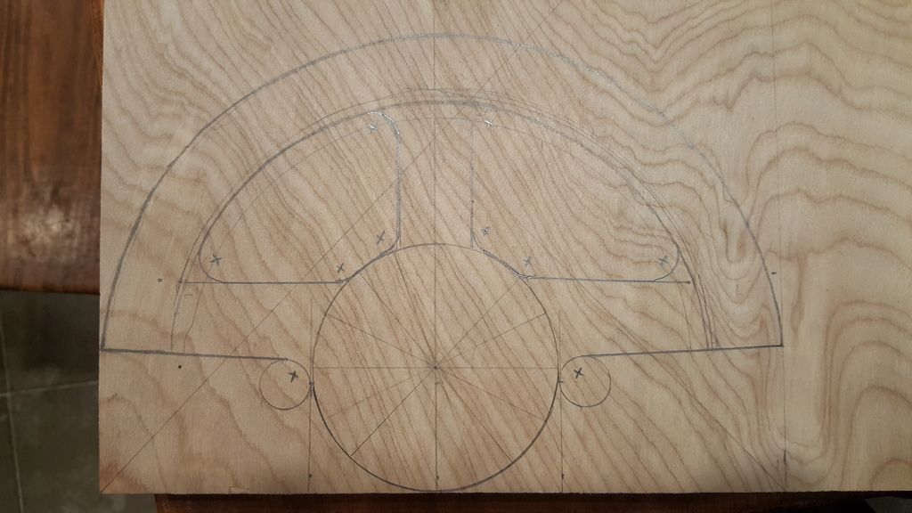


I decided to just do the layout myself, instead of using the templates provided, since my first try using the template resulted in an uneven car body front.  I'll show that in a moment.  All I did was take measurements off of one side of the steering wheel template, and them transpose them onto the plywood.  I'm trying to use as much leftover stock as possible on this project, to keep my costs to a minimum.  Here, the steering wheel is being made out of leftover oak plywood.  Here it is after cutting, sanding and painting:
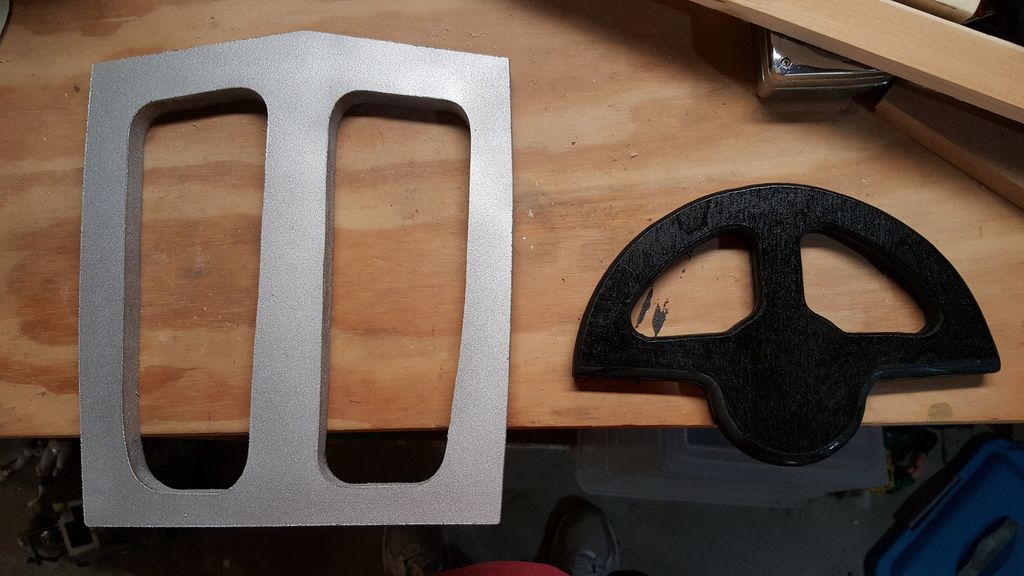

Next to it is the front cowling.  That will attach to the front of the car body.  I went ahead and painted the section to be revealed.  Here is a shot of the front of the car with the painted sections:
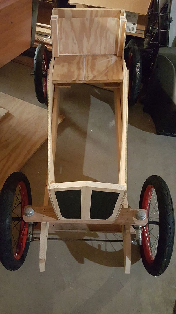

You can also see how the plans address the steering linkage.  I'll need to add the steering column, after I figure out what I'm going to do.  All I know at this point is that I'm not going with the plans that I bought.  Other people have also come to that conclusion and I'll try to mine their blogs for ideas.  You can also see the frame and body and how they come together, as well as the seat arrangement.  Somehow, when I was installing the seat platform, it got out of alignment. Not sure how it happened, but it is glued and screwed into place, so its not coming out.  But it's not a big deal.  I have material to make a seat cushion and back, so they will make up for it being uneven.  I'm not sure if you can tell from this pic, but the part that is painted was made from an original template.  It is uneven, but usable.  This is the part that clued me into how bad the drawings were if I wanted to use them as templates.  It's also a reason that I decided to keep the fenders off of the car (also because I like the hotrods without fenders (the FTF club)).  Here's a sideview of the car:
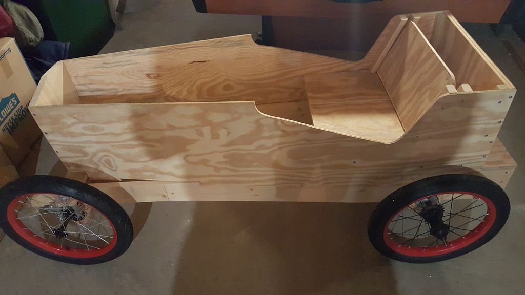

The car is planned to be red like my Chevy pickup truck.  I'll paint the frame rails black, as they should be.  On the other side, I'll have the sprocket and chain exposed.  I'm planning to have a small pipe attached to that side.  I'll use it to simulate an exhaust pipe that runs down the side of the car. The real purpose, though, is an attaching point to the coaster brake from the donor bicycle.  If you remember, coaster brakes work by pedalling backwards until you get resistance. This works by way of that small metal piece that is connected to the wheel hub and bolted to the bicycle frame.  Since there is no bicycle frame here, I need that pipe to bolt the brakes to.  I'm just hiding it by making it look like the exhaust pipe.

That's all for now.  It had been a while since I posted anything, so while it's not Chevy truck related, it did take my weekend.  I'll update progress here, too.

Saturday, July 25, 2015

Solder Practice

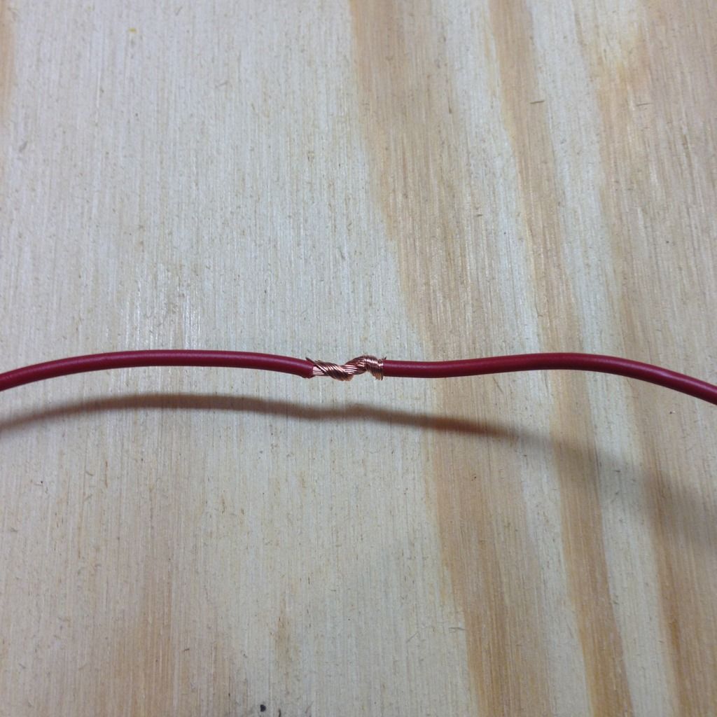
Doctor's orders keep me from physical labor this weekend, so I decided to try something light, while still moving forward on the truck.  I knew that I needed to practice soldering before I start in on my new wire harness, so this was the perfect weekend to start practicing.  After a little online research and talking to my friend who is an experienced solderer, I set out to practice.  I took 2 equal lengths of 16G wire, stripped the ends and physically twisted them together to start an inline splice.  It looked like this:


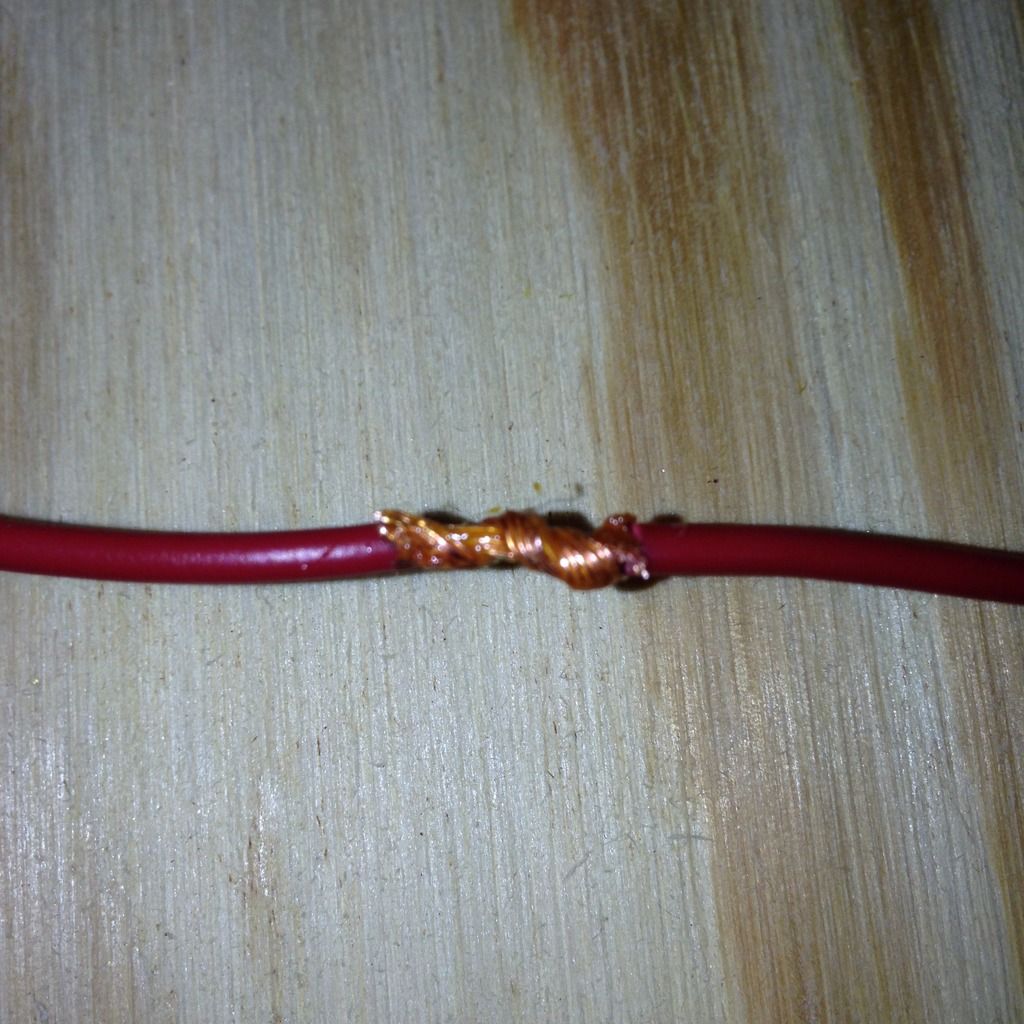
Two things I learned from this part of the practice: 1.  I needed a little more stripped wire than I stripped for my practice, 2. It's harder than it looks to get a nice, neat wire twist.  However, I decided to just keep going with it instead of trying to make it perfect.  The next step was to coat the bare wire with flux.  It looked like this:


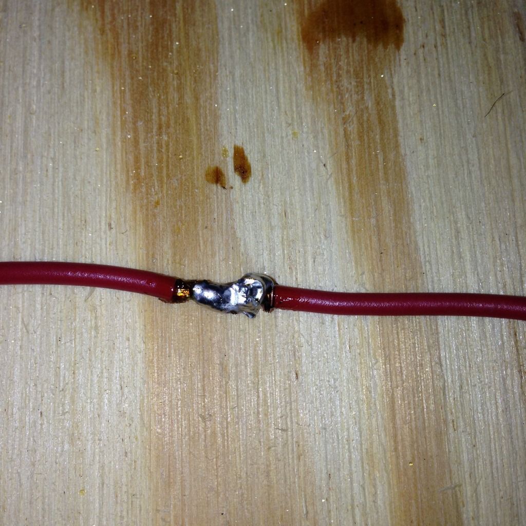
The pic is a little blurry, but you can see the flux is pretty well coating the exposed wires.  Next was to actually solder the wires.  It looked like this when I was done:


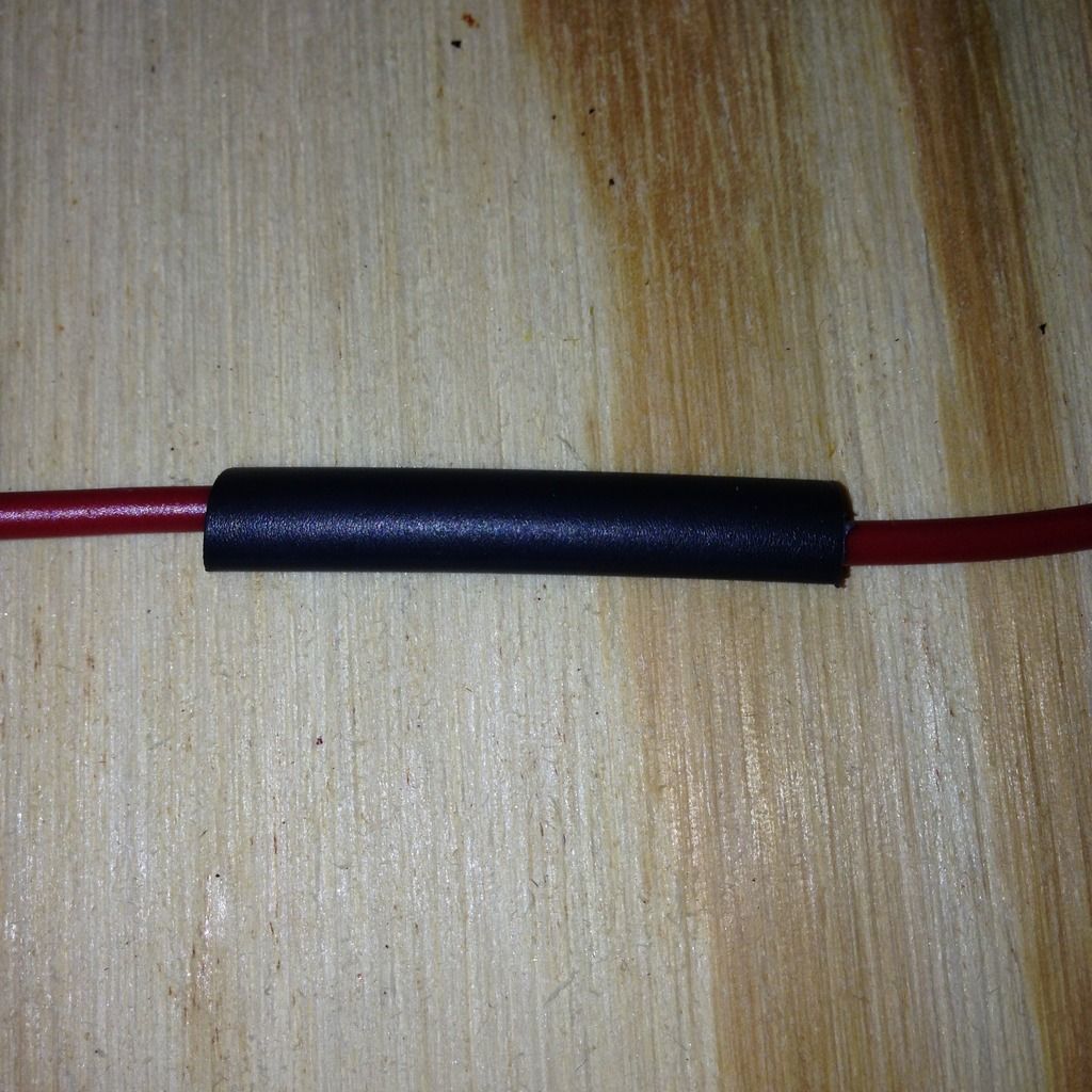
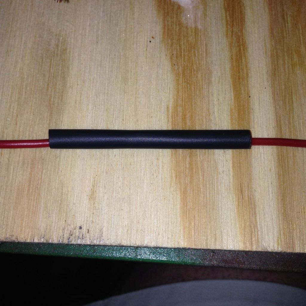
It's not pretty, but the wires are completely soldered.  I am a little worried, though.  I am trying to do the soldering without overheating the wire insulation.  Clearly, I'm not an expert, but the insulation on the wires next to the solder joint look a little overheated to me.  Plus there is some extra flux on the wire on the left side.  I don't know if any of this is a problem or not.  It was my first try and time will tell, which is ok, since I'm not going to be soldering on the wire harness for several months.  That gives me more time to practice and get it right.  Anyway, still in the spirit of keep moving forward, I got out the shrink wrap tubing.  I cut a piece that covered the solder joint and the adjacent wire insulation.  It looked like this before heating:


After heating:


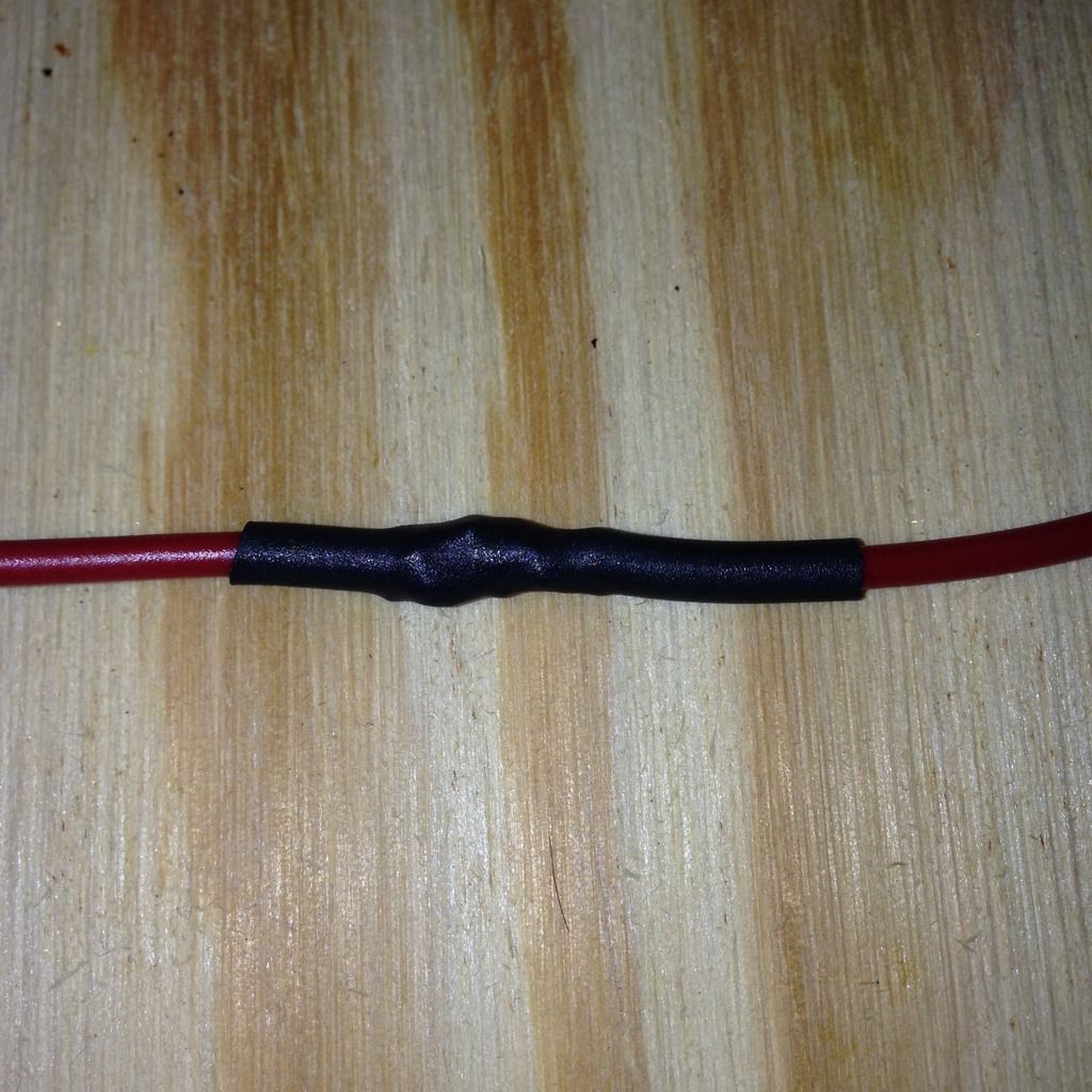
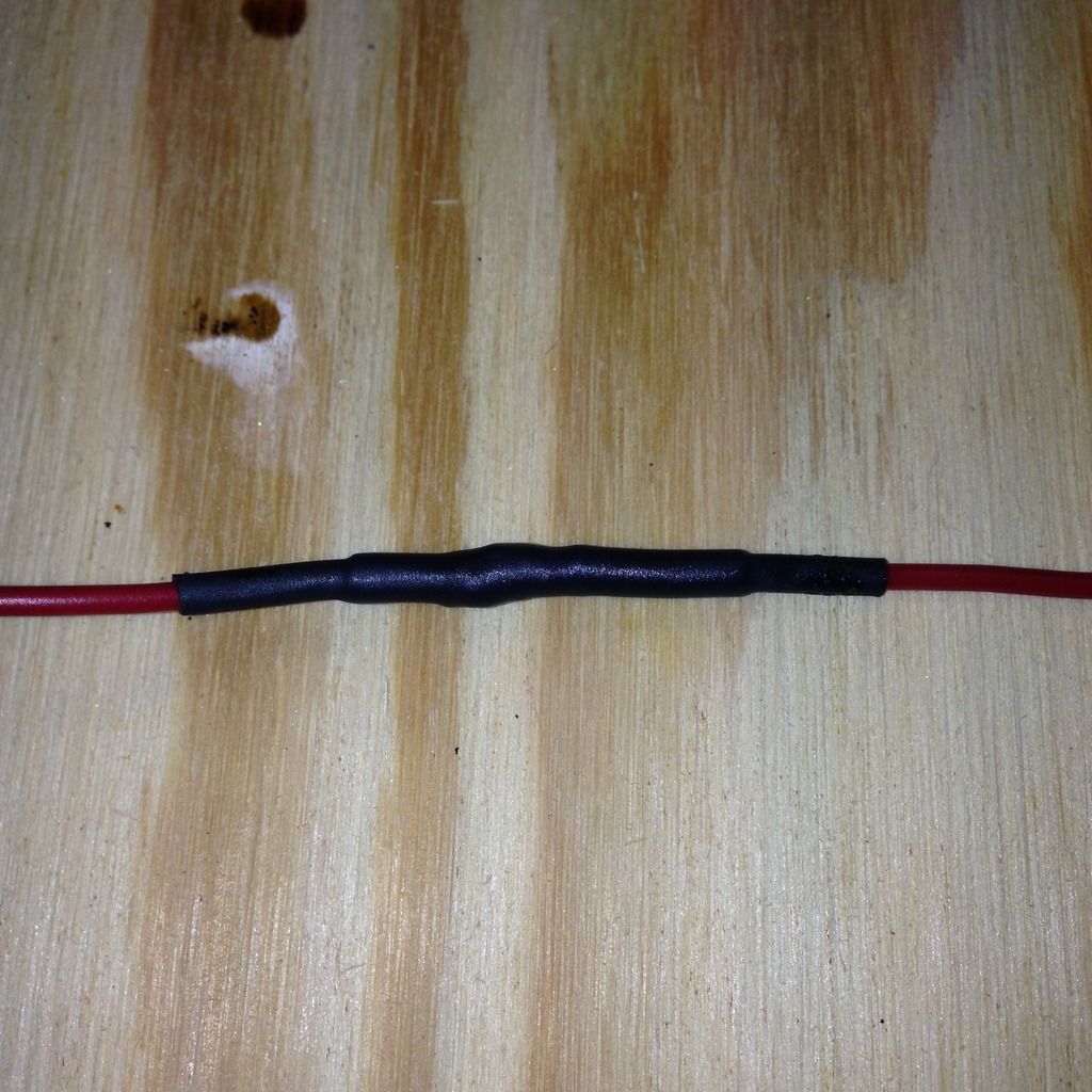
Once again, it looks a little "sweaty" to me, like it's been overheated.  However, it did conform, revealing my lumpy solder joint.  But it did conform!  In an effort to make a water resistant splice, I put a second, longer piece of shrink wrap tubing over the first.  It looked like this:


After heating, you can clearly see the underlying shrink wrap tube.  It looked like this:


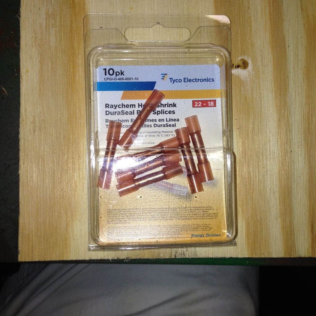
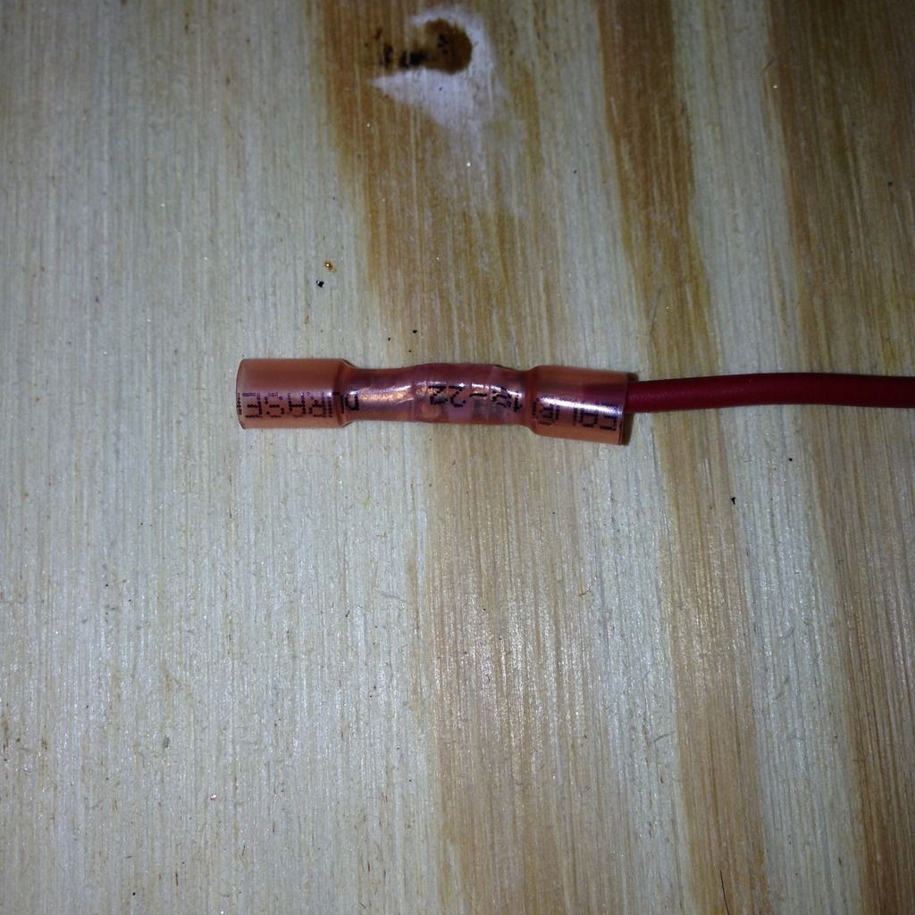
Not a bad first attempt, but clearly it could use some improvement.  Just to round things out, I got out a butt splicing crimp connector to see what the difference would look like.  I used these connectors:


When crimped onto the wire, it looked like this:


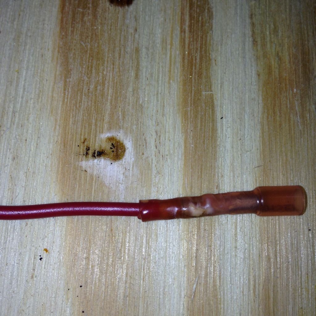
The package says that the cover is heat shrink material, so I gave that a try too.  It looked like this:


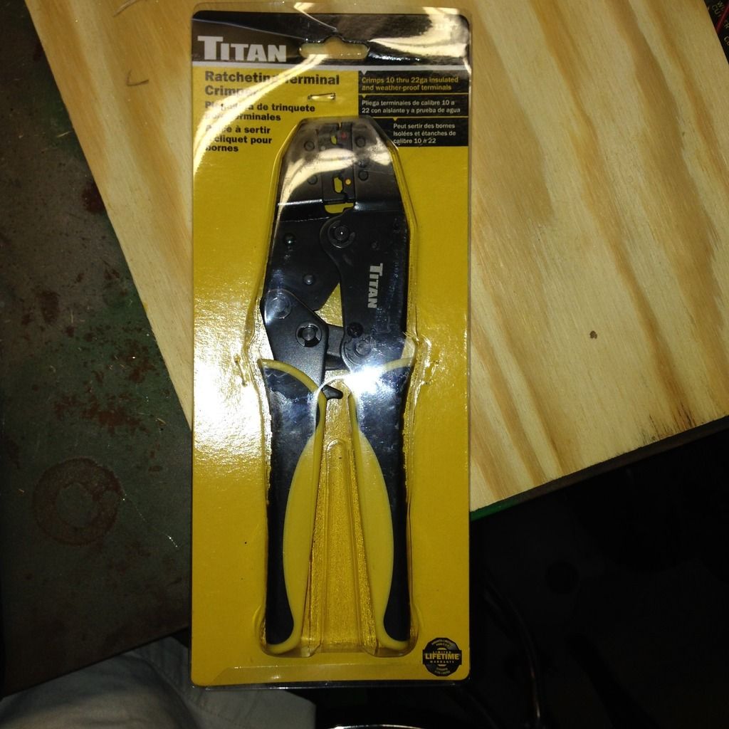
It did shrink, but looks a little "melty" to me.  Also, in the first crimp pic, you can see that it was made for 18-22g wire and I jammed a 16g wire in there, so it was a tight fit, and likely not a good connection.  But it's just a test....  In case you were wondering how I got that massive crimp, I used the crimping tool that I got from Speedway Motors when I ordered my wire harness.  It looks like this:


Once again, I have to apologize for the rotated pics.  Apparently, Photobucket is not impressed with iPhone pics.  It randomly rotates pics (like the crimping tool pic) and when I manually rotate them in photobucket, they look right, but post wrong.  This is also obvious in the crimp pics as they are rotated 180 degrees from each other, which is something that I did not do when I took the pics.  Oh well, it's free....

That's all for now, got to rest.  Yeah, right!

Sunday, July 19, 2015

Hazy, Hot and Humid... Not Truck Wrenching Weather.

The three H's ruled the day today, but it is summer.  Got the grass cut, but simply too hot to be in the garage doing anything!  No pics either, just trying to stay cool.  Will pick things up again, when the summer temps cool off a bit.

OK, maybe one pic, a little mind over matter to help with the heat...


A little reminder from a couple of winters ago.  No matter how hot it is now, the cold weather will get here eventually.

Sunday, July 12, 2015

A Dash of Dash (Panel Trim)

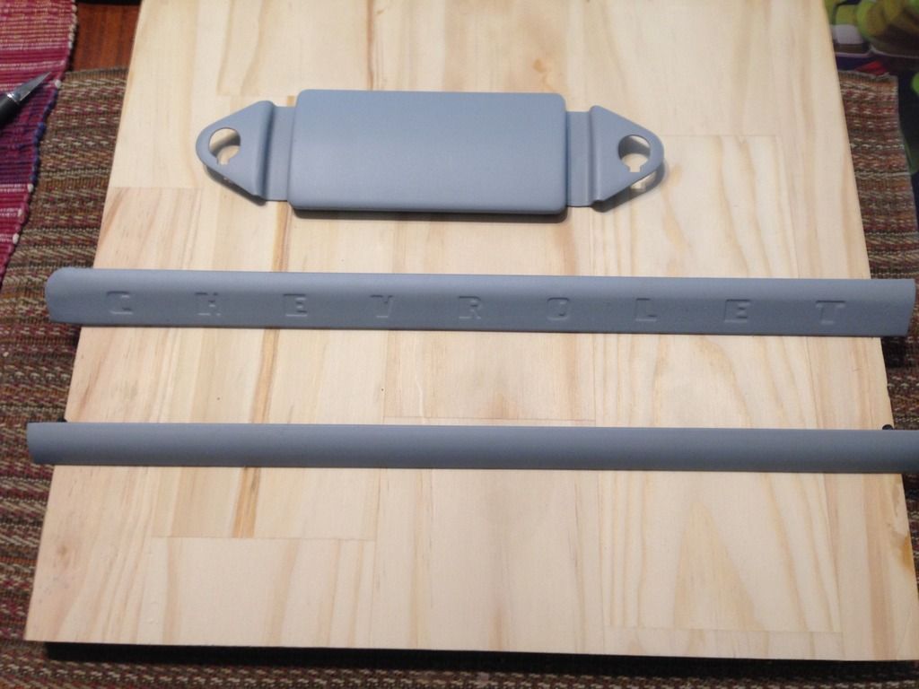
Here's the last of the quick hitting projects, some dash panel trim and the radio delete panel and attaching bolts.  Once again, here's what it looked like installed in the truck when I got it home:


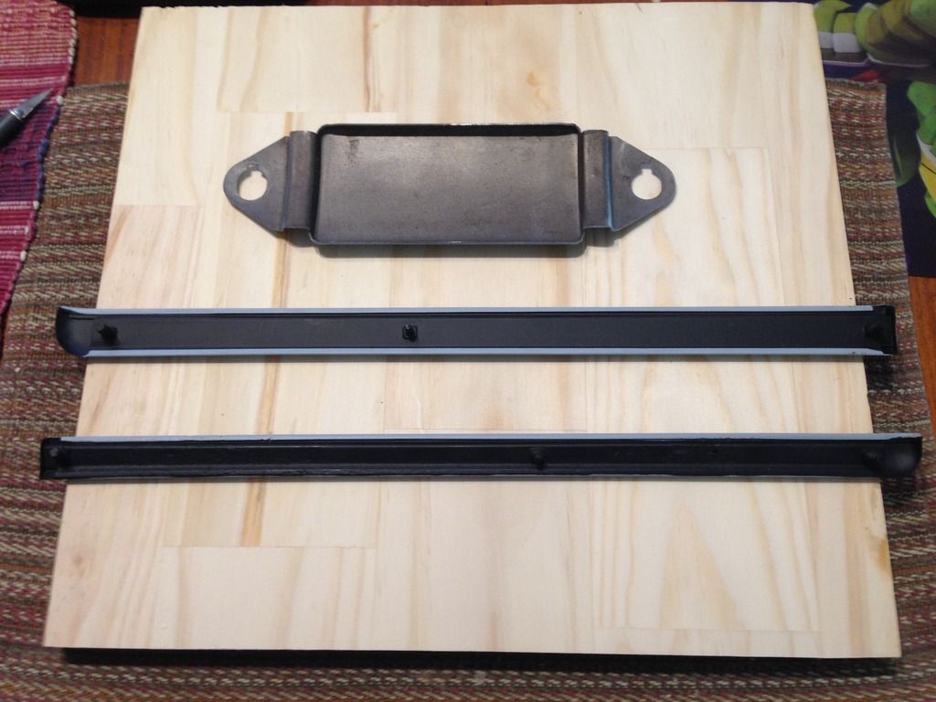
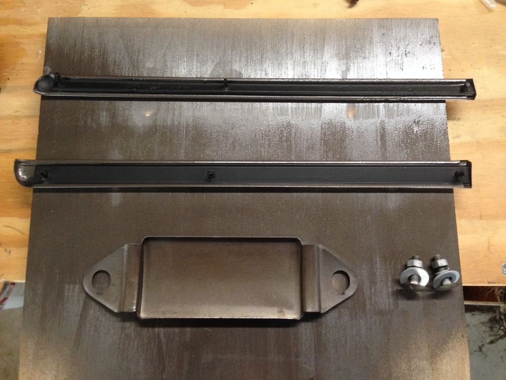
It's kinda hard to tell from the pic, but there is an upper piece of trim, a lower piece of trim and the slotted piece is actually the radio speaker grill.  The 2 pieces of trim hold the grill in place and the ashtray mounts into the grill.  Here are the pieces after disassembly and sanding:


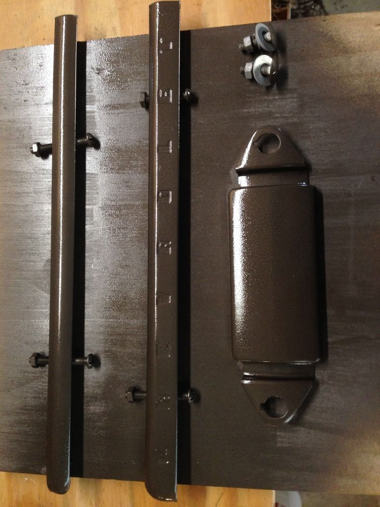
These were sanded and primed 5 years ago.  Also, because these pieces are actually made up of several pieces of metal, they are hollow.  To get the rust out of the inside, I used Evapo-Rust.  I soaked the parts in the Evapo-Rust until all of the rust was gone.  After it was gone, I rinsed the parts off, dried them with a hair dryer until I was sure that the insides were completely dry.  When I was sure that they were completely dry, I poured paint down the inside to coat the entire inside. It was an attempt to seal the inside surface and prevent rusting again.  After that, I was able to prime and paint the underside.  It looked like this:


(Sorry, I don't know why the pic is rotated, but I can't get it to go the right way....)

I did not do anything to the underside of the radio delete plate, as it wasn't rusted.  Fast forward 5 years and I taped off the backs of the pieces and painted the fronts.  It now looks like this:


Here are the undersides after painting:


That's all for now.  Apparently Photobucket has gone insane.  Pics that look fine there are now rotated here.  Not sure what is going on, but hope it gets resolved quickly!

I'm going to order the vinyl letters for the upper piece of trim.  For 1953 they were white.  When I order those, I'll also order the dome light gasket and some other odds and ends that I need. Trying to make the shipping costs more economical.  Also, I still have the radio speaker grill and the glove box door to work on.  Those still have some rust on them, so they are not yet ready for primer or paint.

Saturday, July 11, 2015

The Smoking Lamp is Lit

Another quick turnaround project....  Like the horn button, I had removed the ashtray early on after getting the truck.  Like the rest of the interior, it was in pretty rough shape.  Here's how it looked when I got the truck:


It was actually kind of comical.  The guy that found and bought the truck to resell it had spray painted primer everywhere.  I guess he was trying to hide the rust and tidy up things a bit. However, he didn't go to much trouble in prepping before spraying.  Here you can see a bunch of pencils sticking out of the ashtray.  When I pulled it, it was full of old cigarette butts, too!  When I got it out, I noticed that the actual ashtray body was a real mess, with rust through and pin holes everywhere.  So I cleaned it up and then decided that it was too far gone to salvage and ended up buying a replacement body on eBay.  I was able to clean up the face and handle of the ashtray. The partially cleaned face looked like this:


I say partially cleaned because you can clearly see discoloration on the face of it.  This pic was taken 5 years ago and frankly, I can't remember how clean the face was when I coated it in primer.  However, I don't usually leave any discoloration when I'm cleaning, so I'm assuming it was all gone.  Also, when I looked at it today, there was no indication of any further rusting.  So I feel good that I got it all when I cleaned it 5 years ago.

Then it was simply a matter of unscrewing a small screw on the inside of the ashtray that holds the handle on.  (The handle then squeezes the face to the ashtray body.)  Once the handle is removed, the face comes right off the ashtray body.  Then, like the horn button, it was off for paint.

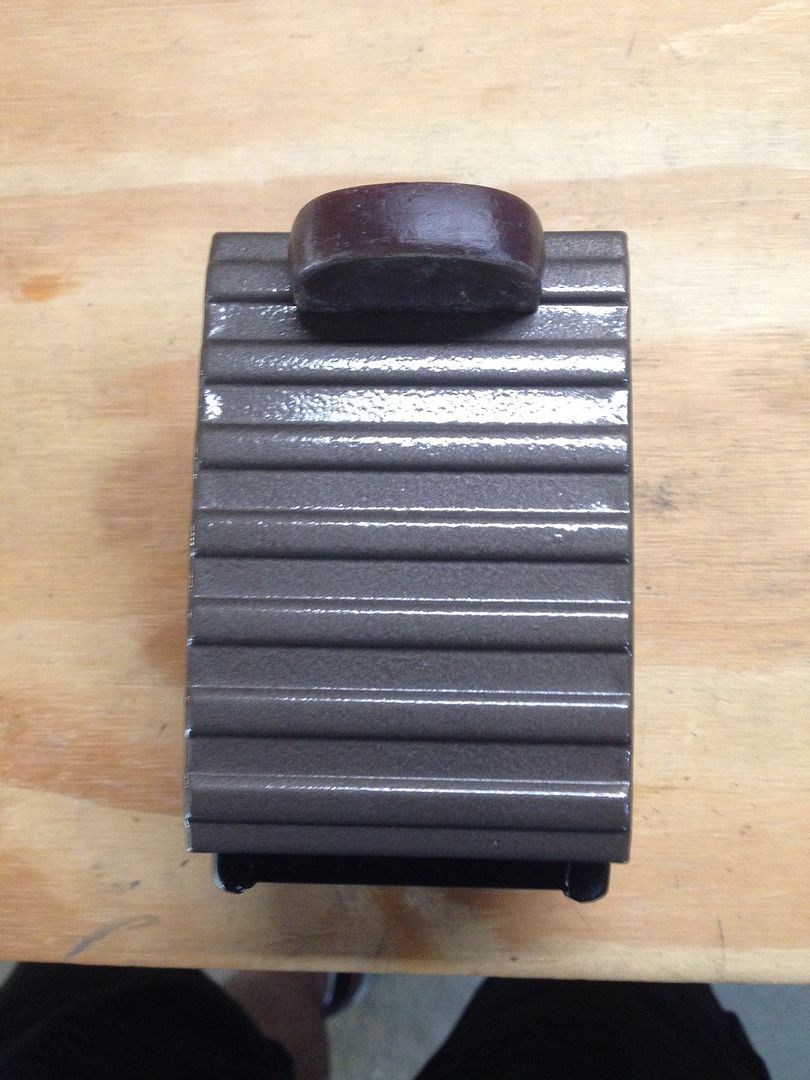
Here it is after painting and reassembled onto the ashtray body:


I bet it's been a long time since you've seen an ashtray that was actually meant for cigarettes and ashes.  Here is a top shot, looking down:


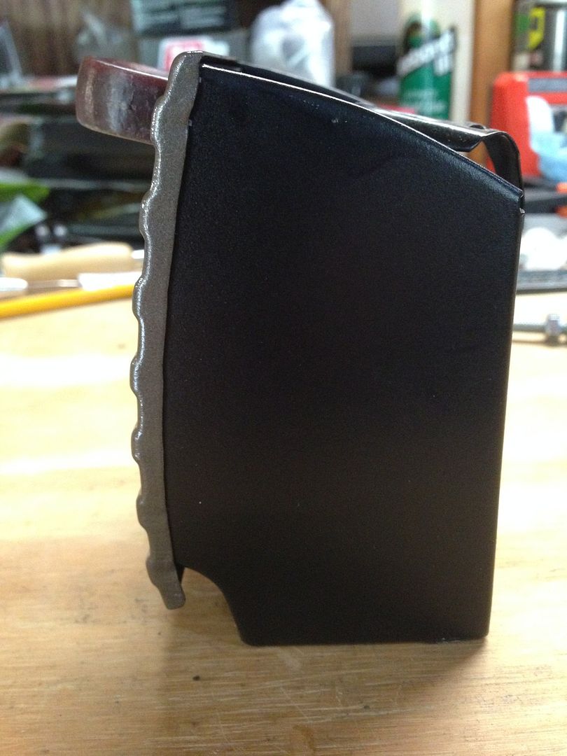
Here is a side view:


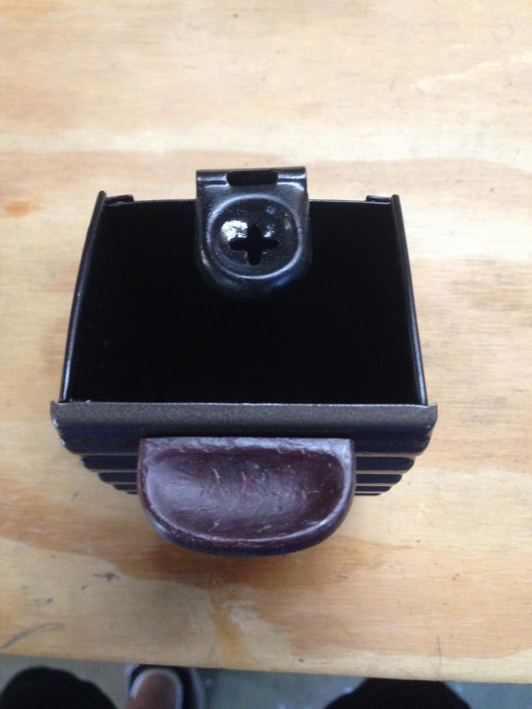
The original ashtray was not painted on the body.  I went ahead and primed/painted the replacement body to prevent any further rusting.  In the next shot, you can see the small screw that holds the handle to the ashtray body and squeezes the face plate to the body.


So that's it for this quick edition.  I've got some dash trim pieces that are masked off and the first coat of paint is drying.  I'll try to get the final coat on them tomorrow and have another post for those.  It's been very gratifying to be able to finally finish these small projects that I started so long ago.  Once the paint on them is fully cured, I'll package them up and store them out of the way.  That will free up some much needed shelf space, which is a good thing.

Beep Beep, Beep Beep, Yeah!

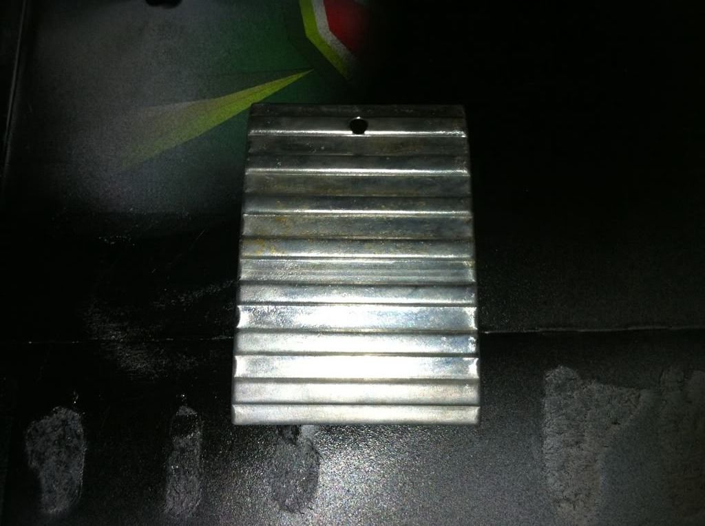
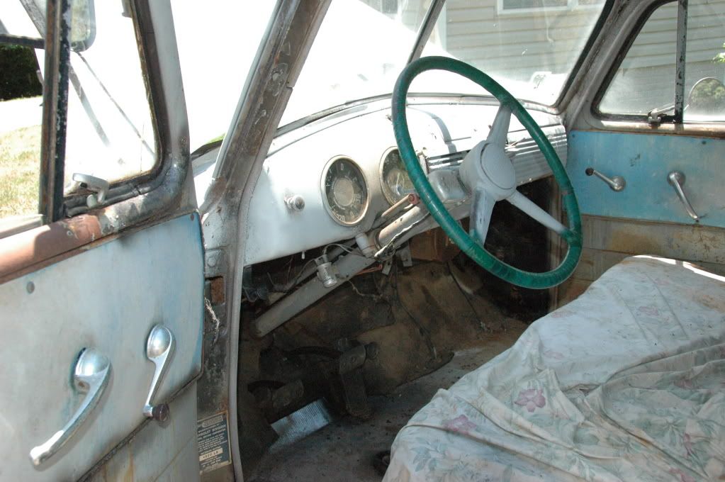
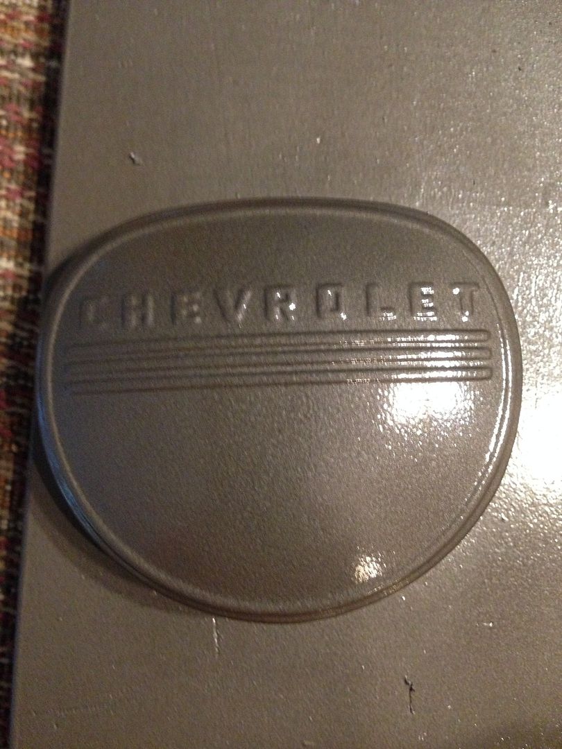
Here's another quick post on a quick project that I started about 5 years ago and finished yesterday. The horn button!  Pretty simple, huh?  Here it is as it sat in the truck when I got it:


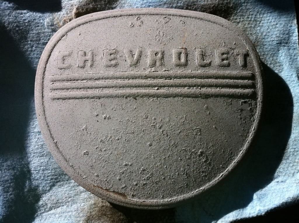
Here it is after I took it out of the truck 5 years ago:


A quick sanding and some primer got it to this stage:


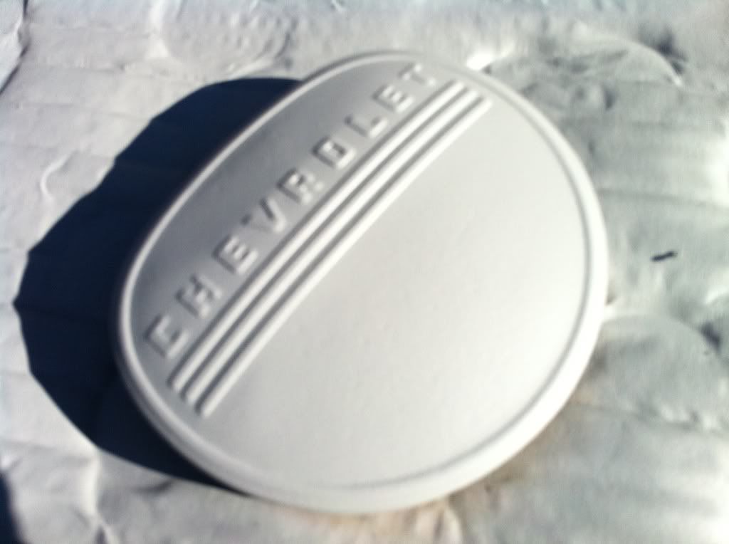
Then time passes....  It sits on a shelf in the basement....  Now that I found a close match to the interior paint in a rattle can, it's time to finish what I started.  Here's the result:


The underside is painted, too, except for the center of the button, which is necessary for contact with the switch.

I'll let the paint cure for a couple of days.  Then it's back to the shelf, although packed away this time. I had toyed with the idea of highlighting the letters and decorative bars in an ivory color, but am now leaning against the idea.  I had a mild incident while painting the button.  A small piece of debris somehow found its way onto the button and dinked up the paint.  I had to wait for it to dry, lightly sand off the debris (used 220 grit with a very light touch) and then respray it.  Turned out well and I don't think that you can see where I sanded and resprayed it.  So all's well that ends well, but I don't want to mess it up again trying to make the letters stand out.  That wouldn't be a quick fix....

Sunday, July 5, 2015

Taking a break from the brakes and making some light

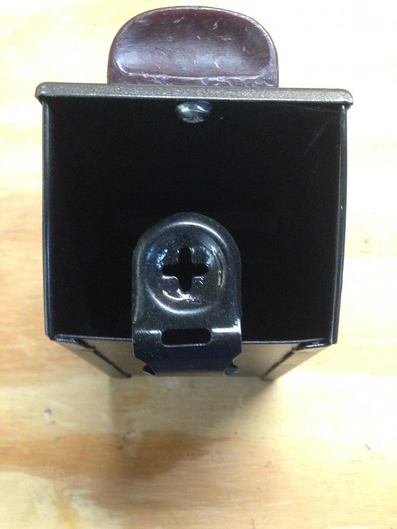
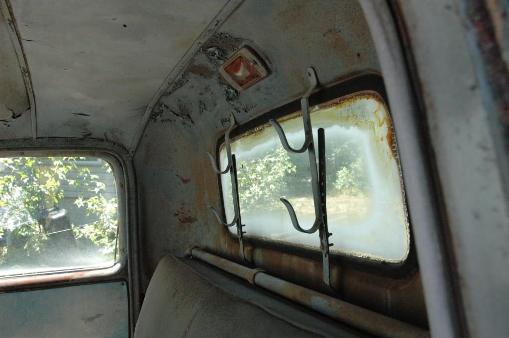
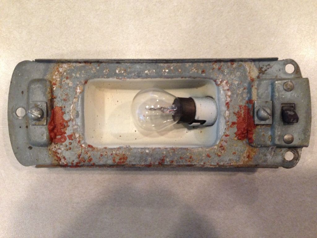
Being a holiday weekend, I knew that I wouldn't get much time to work on the truck, even with extra time off.  So I decided to work on a small project.  I need to clear out everything from the cab, so that I can pressure wash the inside.  This includes the seats, instruments in the dash, gas tank and dome/courtesy light.  Everyone knows it today as the dome light, but chevy called it a courtesy light back then.  This is how it looked when I got the truck home:


You can see the light is covered in some kind of rose colored something.  When I took the light apart, the rose colored something looked like a glob of dried latex paint.  It covered most of the glass lens and parts of the light housing.

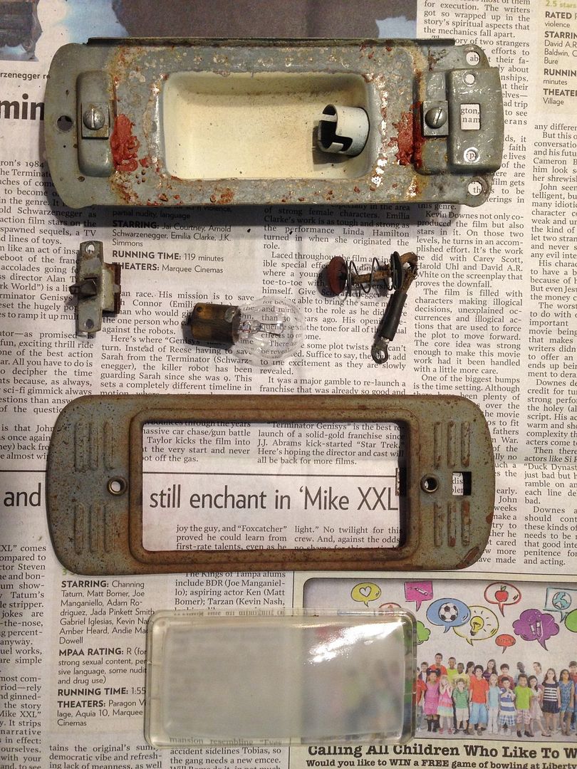
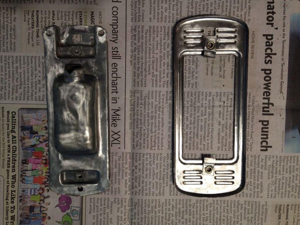
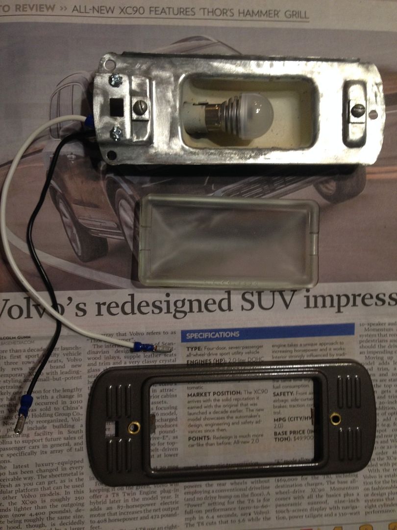
When I got the light out of the truck and apart, it looked like this:


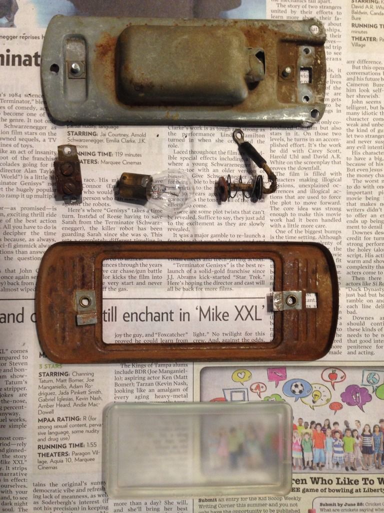
The light housing is on top.  You can clearly see the rose colored material.  Next are the switch, 6v bulb and socket wiring.  Below that is the cover, which holds the lens.  Below the cover is the glass lens.  The underside of each piece looked like this:


In these photos, the glass lens had already been cleaned of the rose colored material.  It was in thick globs inside of the lens.  It dissolved easily in Formula 409 cleaner.  It sort of dissolved in plain water.

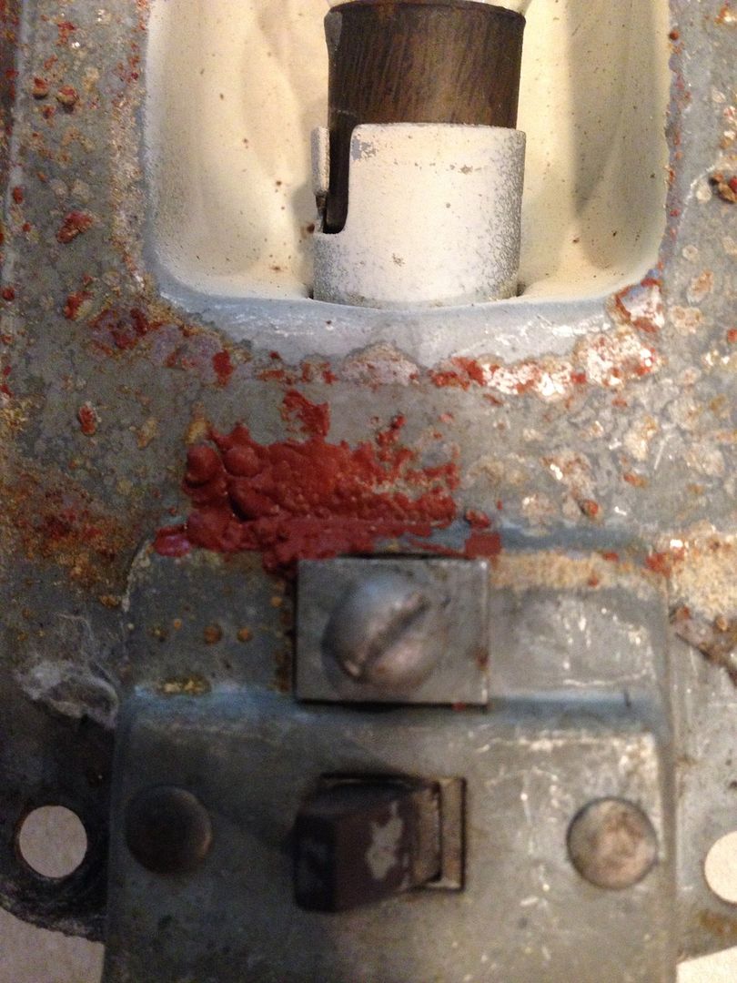
Here is a close up of the  light housing:


Here is a close up of the light housing switch:


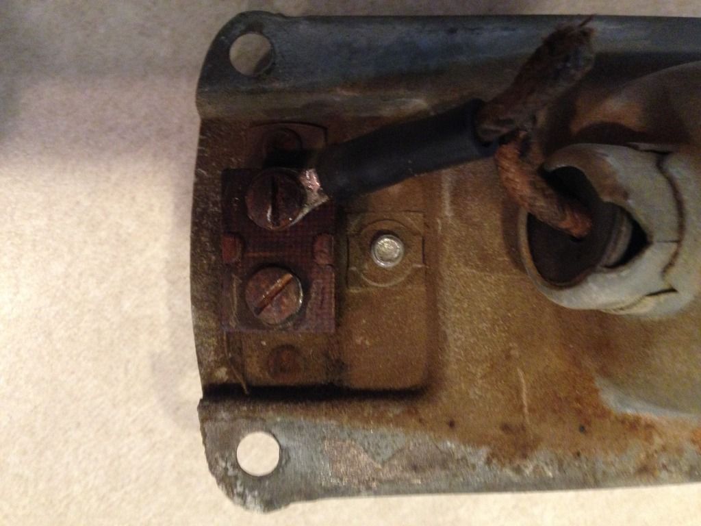
Here is a close up of the switch underside:


The switch is a single pole single throw (SPST) type of switch.  The truck wiring brought one power lead to the switch (the terminal that is now empty).  The other terminal connected to the positive side of the light bulb through the socket wire harness.  Grounding was accomplished through the light housing frame and into the truck body/frame.  The switch would simply connect/disconnect the power to the light bulb.

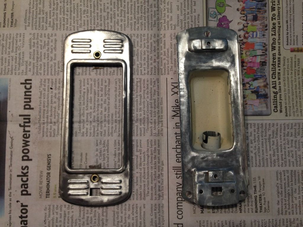
Cleaning consisted of light application of the dremel and abrasive wheel.  Here are the light housing and cover after cleaning.


A couple of things to note that are now visible:  The screw holes used for mounting the lens cover to the light housing have brass eyelets through them.  I did not clean or remove the cream colored paint inside the bulb area.  I'm guessing it is for reflective purposes and it was in good enough condition to just leave it alone.

Here is the underside of each after cleaning:


Some swirl marks are visible on the light housing, but no one will ever see them, so I just left them.

Here is a close up of the light housing.  You'll notice the new socket wire harness is already installed and the bulb is inserted into the socket.  The bulb is the Sylvania 1156 LED version. The original bulb was a #87, which is a 6 Volt bulb.  I could have gotten a 12 Volt version (#93), but wanted to stay away from the incandescent bulbs whenever possible.  The 1156 uses the same size socket (S8), but the incandescent version would have been too hot for the housing.  So I found the LED version and got it at my flaps.

Here are the three restored assemblies:


You'll note that the switch was left out of the restored light housing.  I originally looked for a replacement or NOS.  No NOS was found and none of the mini or sub-mini SPST switches were a good fit.  Then I realized that the replacement wire harness I already had bought (Speedway Motors 20 circuit harness) used the headlight switch to operate the dome light.  This means that the harness sends both positive and negative leads from the headlight switch to the dome light, obviating the need for the switch at the light.  I decided to leave the hole as it was and not weld it closed, in case someone down the road wanted the switch at the light.  The wiring, then, is positive (black) to the light socket wire and ground (white) to the light socket housing.  The cover was painted with Rustoleum Dark Bronze Hammered paint over Rustoleum Automotive Primer.  I still need the internal gasket and will order it when I'm ordering other stuff.  Several of the companies sell them.

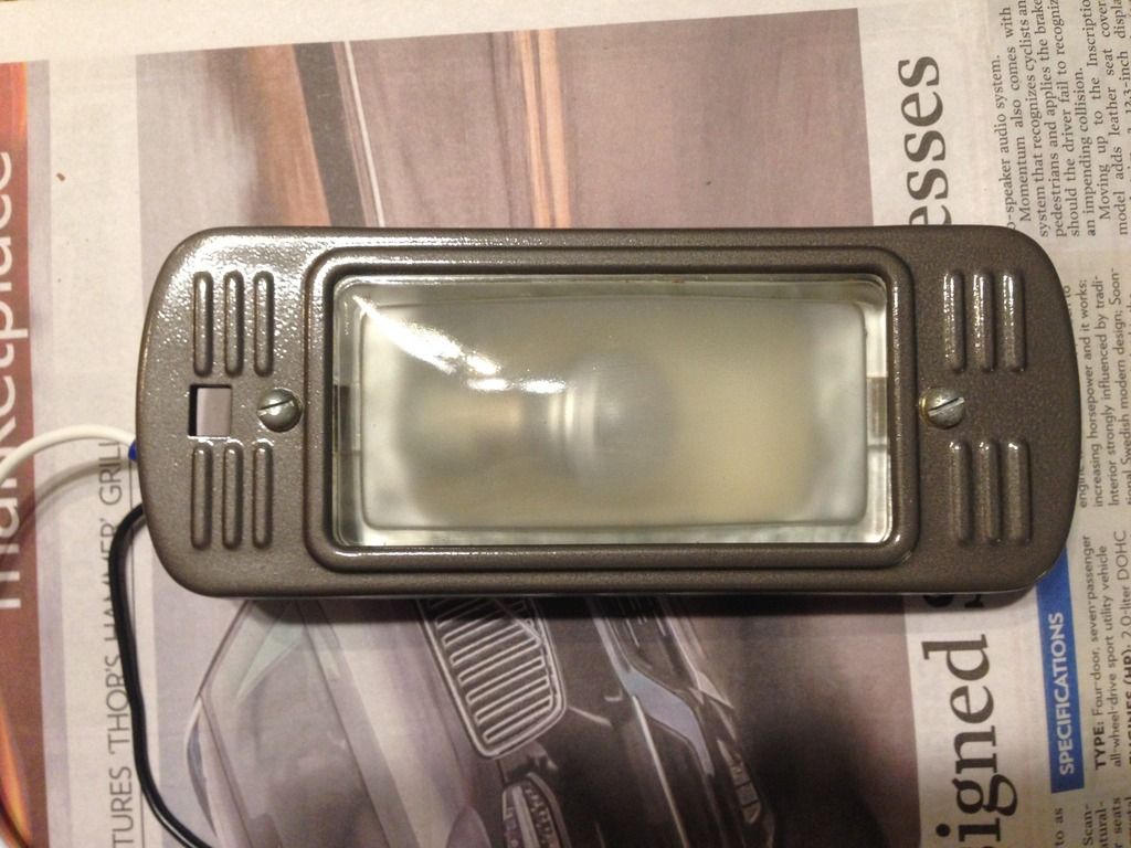
Here is how it looks assembled:


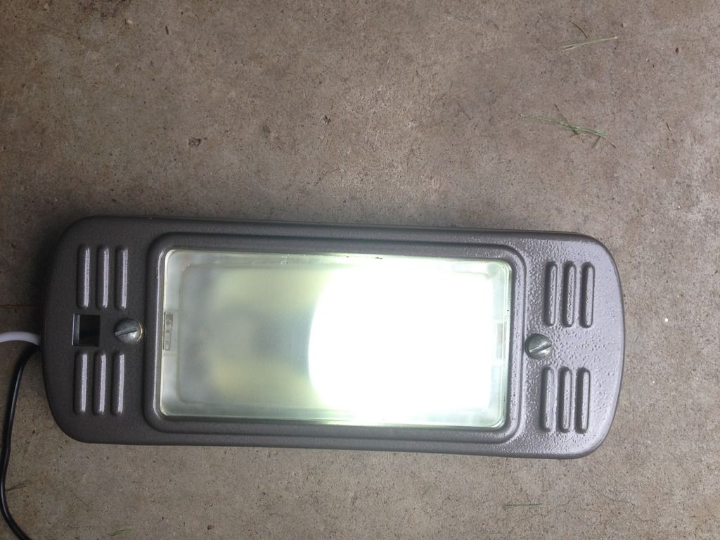
Here is how it looks attached to the battery and lit up:


So that's it, a quick little project to take a break from doing the brakes.  Next weekend it will be back to the brakes.  For now, the light is put away waiting for me to need it again....

Sunday, June 14, 2015

John Henry is a Steel Driving Man (and he's working on my brakes)

I started working on the front brakes this weekend and so far, it's been pretty frustrating.  Armed with my experience replacing the back brakes, I thought I knew what to do on the front set.  Boy was I wrong....  After removing the front wheel, I started off by hitting all of the mating surfaces that I could see with Kroil penetrating oil.  A little prying with a pry bar and nothing.  A little banging with a deadblow hammer and some more prying leads to nothing  Add more Kroil and move to the other front wheel while this one soaks up the Kroil. Repeat procedure on that side. Nothing.  Back to the first side.  Nothing.  More banging with deadblow, more prying.  Nothing. Back to the second side for more of the same.  Nothing.  All the while, I'm thinking to myself that the alignment studs look like they've been peened over.  Nah, just my imagination playing tricks on me.  After all, it was pretty hot out there!  Back to business.  Repeat all of the above. Nothing. Three hours later, I give up in frustration.  Then, after cleaning up a bit, I hit the truck forum and discover that I wasn't imagining things.  The studs were peened over by the factory!  Holy cow, I've just wasted the entire day.  Nice.

The second day of the weekend brought some success.

I got out the Dremel with a hefty cut off wheel and got down to business.  I didn't want to use a full size grinder, because these studs are between the wheel lugs and I didn't want to damage any of them. So with Dremel in hand, I got to it.  Took about an hour to grind all three studs flush with the brake drum.  So now the moment of truth...a little prying and...nothing!  That meant getting the drill out and drilling out what remained of the studs.  That took another 15 minutes or so.  With pry bar in hand I give it one more try...and VOILA!  With an audible crack, the brake drum broke free of the remnants of the studs!  After that, the drum easily came off the wheel hub.  A quick inspection revealed that the shoes were worn paper thin.  I doubt that they had ever been serviced.  I buttoned them back up and cleaned up.  Next weekend I'll replace those internals, grind off the studs on the other side and replace those internals.

One thing that I was able to do was to remove the rubber brake line hoses and the final pieces of steel brake lines.  After I get the brakes rebuilt on the front wheels, I'll add the remaining replacement brake lines and the new master cylinder.  That should be the last of it.  I don't know if I can get it all done in one weekend, but will give it a shot.

Next weekend, I'll take some before and after pics of the studs.

Saturday, May 30, 2015

Dr. Strangelove: or How I Learned to Stop Worrying and Love the Crud

Working on a 62 year old truck, that blew an engine sometime in it's prior life, had it replaced, then sat in a field for over 20 years, will be a challenge sometimes.  The level of "crud" that has built up is amazing.  So how do I know the engine blew at some point?  First, the serial number on the block indicates it is a Chevy 235 cu in inline 6 that was cast and assembled in 1957.  So my 1953 Chevy truck came to me with a 1957 235 engine installed, instead of the 1953 216 cu in inline 6 that the factory gave it.  Second, the entire underside of the truck is covered in oil, grease, mud (mud that is made from dirt and oil, not water) and the remnants of the plants that grew up around it while it was sitting in the field.  You might think that so much oily crud would be a bad thing.  In a certain perspective it is a pain in the butt to clean.  But for preserving the metal in the truck, it was a Godsend!

While removing the brake line that comes from the master cylinder to the junction block located on the frame rail, I had to first remove over a 1/2" thick layer of the crud to get to the screws that held it in place.  Here is a pic showing half of the crossmember cleaned of the crud:


You can see the crossmember with the brake line formed to the shape of the crossmember.  If you look closely in the upper right of the pic, you can see the metal tab and screw that hold the brake line to the crossmember.  There is a second tab and screw on the left side.  In the top of the pic, you can see the transmission drain plug.  The shine is that layer of oil that I was talking about.

On the bright side, the metal underneath the crud is completely rust free.  Too bad the whole frame wasn't covered!

I was able to cut the brake lines at the junction block and get the nut/lock washer undone, so that the junction block is now free.  It's been cleaned and is ready to reinstall on the truck.  The crossmember has also been completely cleaned.  The next step is to get the front end onto jack stands so that I can get the wheels off and get access to the rubber brake lines and the last remaining steel brake lines. Once those are off, I can start installing the new steel brake lines, the old junction blocks on the frame rail and the master cylinder and the master cylinder itself.  That will probably have to wait until next weekend.

Also, the parts to rebuild the front brake assemblies are on order and are due to arrive by the end of next week.  This order is similar to the one from Christmas, as it contains new springs, star adjusters and wheel cylinder attaching bars.  To round out the refurb, I'll have to go to NAPA and get the brake shoes and new drums.

All in all, I'm closing in on the end of the brake rebuild...or at least I have a plan.

Saturday, May 16, 2015

Brake Line Installation Begins Today

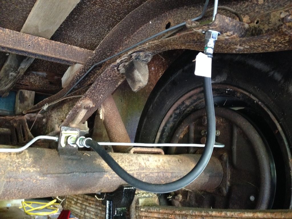
Today I started installing the brake lines.  This is a complete replacement of the brake lines.  The only parts that are being reused are the junction blocks and banjo bolts.  I am replacing the copper washers that go on either side of the junction blocks, though.  I started in the rear of the truck and am working my way forward.  I'm to the junction block that separates the front and rear wheels.  I haven't removed that brake line yet, so that is where I stopped.  Here are some before and after pics.

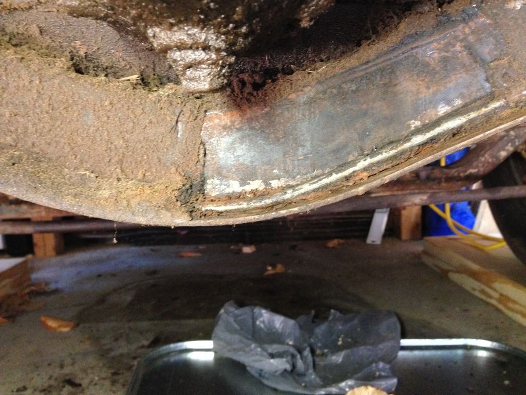
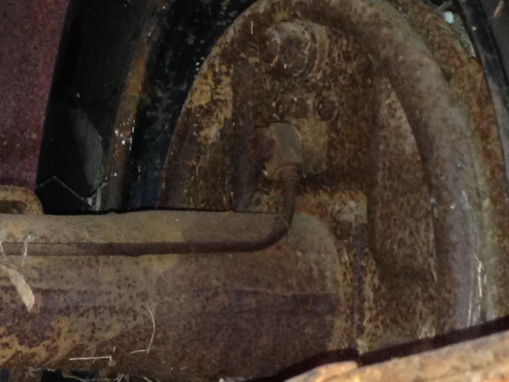
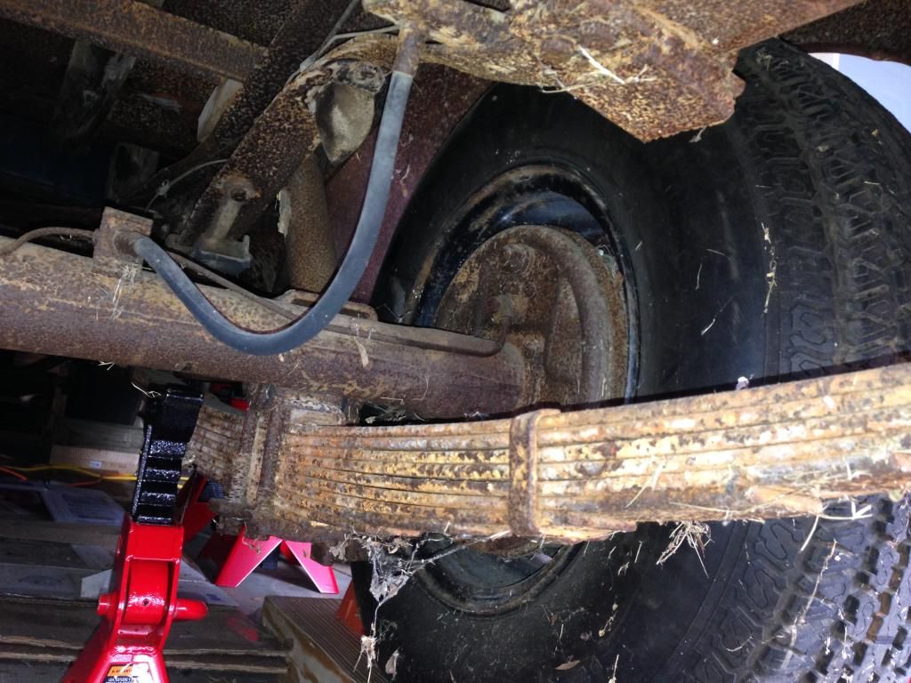
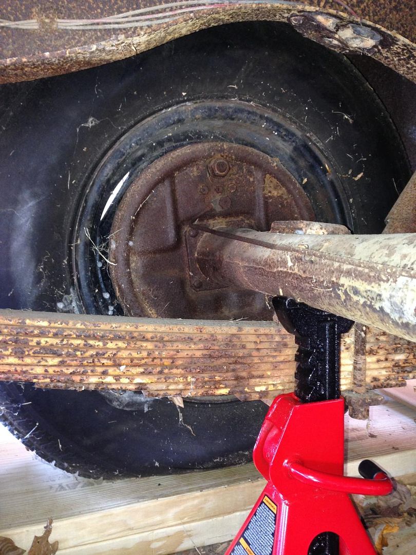
Right rear before replacement:


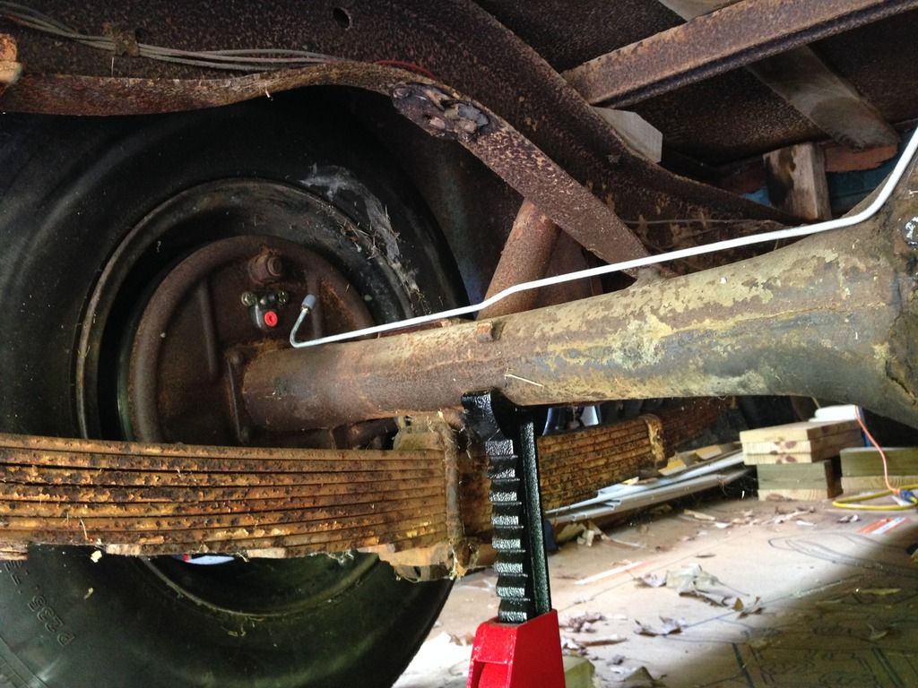
Right rear after replacement:


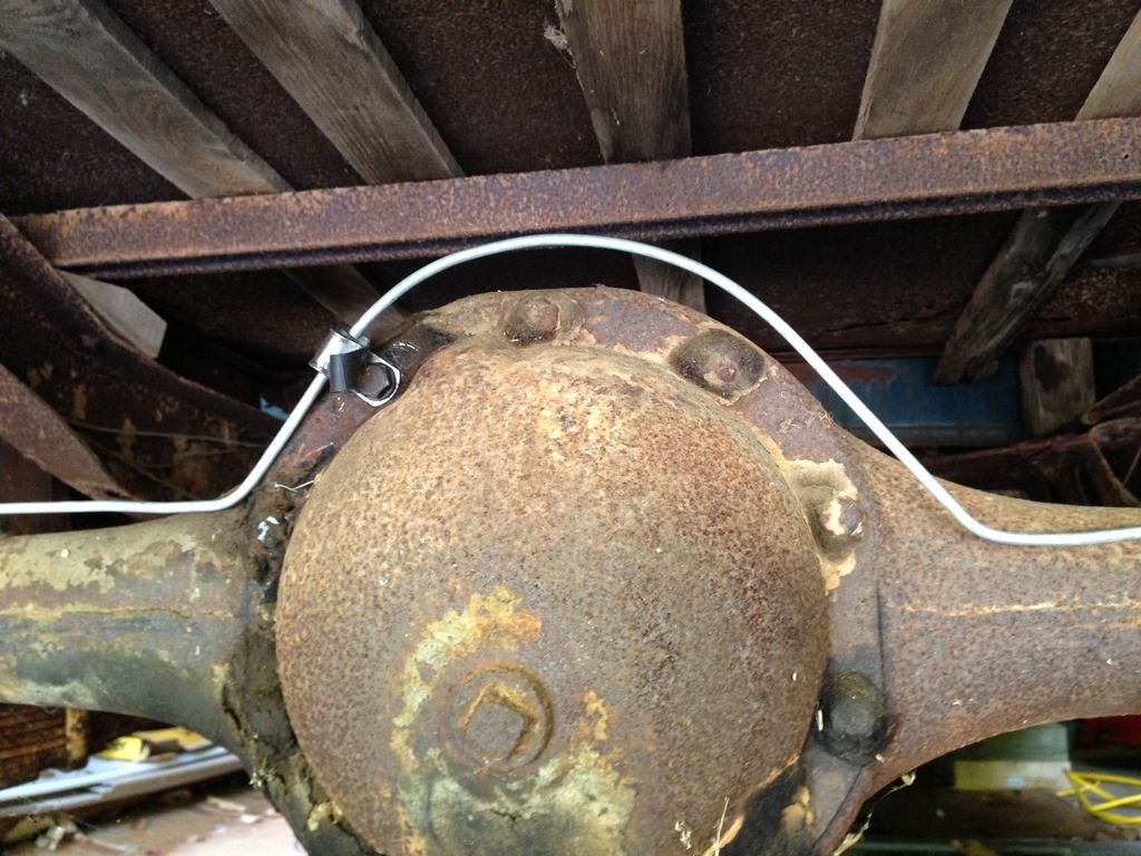
Differential with brake line before replacement:


Differential with brake line after replacement:


Left rear wheel before replacement:


Left rear wheel after replacement:


You can see that the banjo bolt has not been attached to the left rear wheel yet.  Somehow, I managed to lose the copper washers that I need to reattach the banjo bolt and junction block to the wheel cylinder.  So I'll run by the auto parts store and get some more.  They'll need to be annealed before I use them, but that only takes a few minutes to do.  In this pic, you can see that the replacement brake lines come from the manufacturer with rubber covers installed on all of the fittings.  This is good, because you are sure that nothing has gotten into the brake lines that might clog them up.  The color or the cover also identifies the size of the fitting.  The gray ones are 3/8" in diameter.  There is a brown covered one in the kit, too.  That attaches to the master cylinder and is slightly larger than the rest, I just don't remember how large it is right now.  You'll also note that the wheel cylinder came with a plug, for the same purpose.  Quite an improvement!